Resource Sharing in Server2016 RDSH

I first explored this topic several years ago for Server 2012 which remained applicable through the R2 lifecycle. Now with Server 2016 RDS alive and well, let’s see if anything has changed. What was true then is also true now and way back before when this was known as Terminal Services: a host’s physical or virtual resources are shared to several simultaneously connected users, each of which executing applications installed locally on the server. Remote Desktop Session Host, or RDSH, is what we call “session based” virtualization meaning that each user is essentially provided apps or a full desktop experience, but each user is simply a remote session, all existing within a single Windows Server OS. An RDSH host can be physical or virtual, virtual being more common now as you get the additional benefits of virtualization including clustering and HA. This is in stark contrast to desktop virtualization, aka VDI, in which each user is assigned a pooled or persistent desktop VM that has dedicated hardware resources provisioned from a server hypervisor. RDSH works great for application virtualization the likes of office and web apps. In short, RDSH = a single Server OS that users connect to, all CPU and RAM shared amongst all. Desktop virtualization = several desktop VMs each with their own assigned CPU and RAM.

What comes with Windows Server?

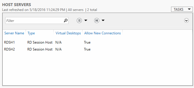
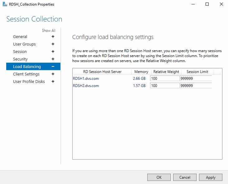
Starting in Server 2008R2, a feature called Dynamic Fair Share Scheduler was introduced which aimed to proactively and dynamically distribute CPU time based on the number of active sessions and load on each. After all, CPU is the resource consistently hit hardest in this use case. Additional drivers were added in Server 2012 to fairly share network and disk utilization, but not memory. This all remains true in Server 2016 with no apparent changes to the base mechanisms. Ultimately if memory sharing between user sessions in RDSH presents a challenge for you, based on user or application behavior, adding third-party tools or Hyper-V + desktop VMs may be a better option. That said, since your RDSH environment will likely be virtual, these elements are controlled on a per RDSH server VM basis. So balancing user load between these RDSH instances is the more important concern as no single server instance will be allowed to overwhelm the host server.
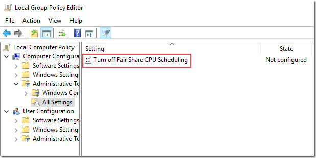
The CPU scheduler can be controlled via group policy, which is enabled by default, but not disk or network, also enabled by default.

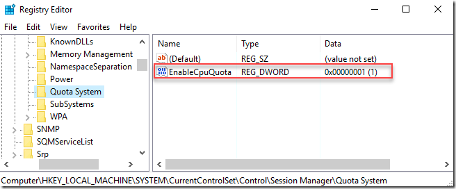
This GPO element toggles the switch found in the registry at \HKLM\System\CurrentControlSet\Control\Session Manager\Quota system:

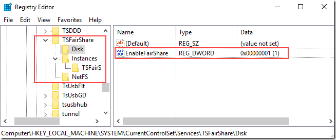
The other Fair Share components, can be found in the registry as well in a different location, each provide a binary on/off switch.

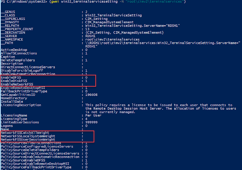
These elements can also be controlled via PowerShell through the command (gwmi win32_terminalservicesetting -N “root\cimv2\terminalservices”). Here I have DFSS disabled but disk and network enabled. Not sure why network shows no value here:

Test Scenario: CPU Fair Share

The output below was generated using the following configuration. Please note this does not represent an optimal or recommended RDSH configuration, it is intentionally low spec to easily showcase this scenario:

  • Host: Dell EMC PowerEdge R630
  • Hypervisor: Server 2016 Hyper-V Datacenter
  • RDSH: 1 x Server 2016 VMs configured with 1 vCPU/ 4GB RAM
  • Users: 3 total sessions represented by RDP-TCP, ICA-CGP/ pfine/b/c in the graph
  • Workload: Prime95 blend option
  • Monitoring: Perfmon captures from RDSH1 VM

This run demonstrates three user sessions executing Prime95, I spaced launches a few seconds apart, ending with all three competing for maximum CPU. As you can see, DFSS does its thing to limit CPU, 50% at two users, 33% once all three are active.

image
Network and disk IO fair share will work similarly should contention arise in those resources. So in a very basic form, as is the case with most Windows-included services, Microsoft gives you the bare functional minimum, which indeed works as intended. To take this functionality any further, you have to look to the partner ecosystem.

What about Citrix?

Citrix offers a number of products and services famously targeted at the EUC space, most notably XenApp and XenDesktop. Speaking of RDSH and user session/ application virtualization specifically, XenApp essentially encompasses the connection of your RDSH VMs running the Citrix VDA (Virtual Delivery Agent) to the Citrix management infrastructure. “XenApp” is the larger holistic solution which includes connection brokering, policies and management. For app and session delivery alone, you still need the RDSH role installed on Windows Server but run the VDA in addition on each instance. Previously resource management was enabled via policies in Studio but this has since migrated to Citrix Workspace Environment Management (WEM), which is the result of the recent Norskale acquisition and now represents the primary Citrix UEM tool. WEM does a whole lot more than resource management for RDSH, but for the context of this post, that’s where we’ll focus. WEM is available to XenApp & XenDesktop Enterprise or Platinum customers which you can read more about here.
WEM requires a number of components on its own, including Infrastructure Services (SQL DB, SyncFx), an agent for each RDSH instance and a management console. WEM includes a utility to create the database, another console for the infrastructure service configuration and finally another console to manage WEM as applied to the XenApp infrastructure. Once everything is created, talking and operational, WEM will require access to a valid Citrix license server before you can use it. Needless to say, WEM is usable only within a Citrix infrastructure.
To get started, make sure your agents are talking to your broker, which is set via GPO on the computer objects of your RDSH VMs. The requisite ADMX file is included with the installation media. Verify in the WEM management console under the Administration tab: Agents. If you don’t see your RDSH instances here, WEM is not working properly.

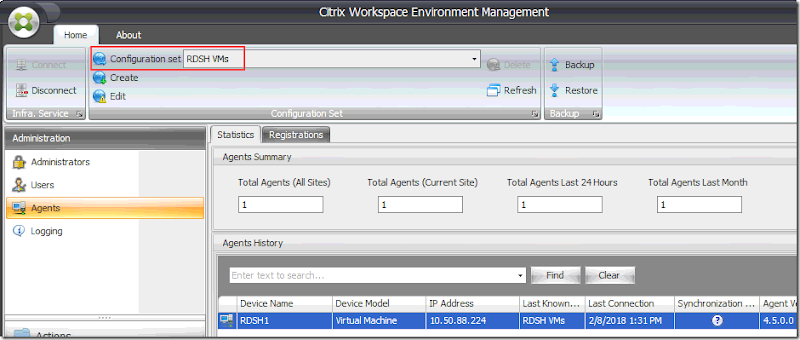
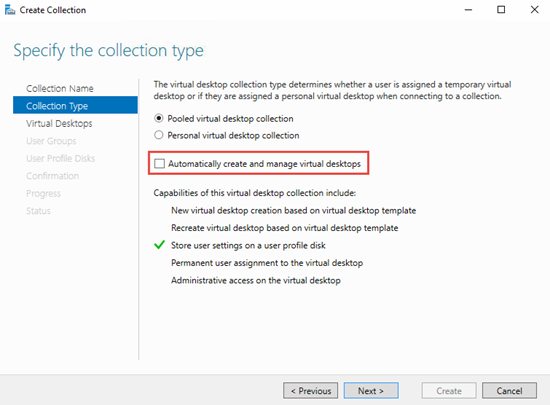
WEM provides a number of ways to control CPU, memory and IO utilization controlled by configuration sets. Servers are placed into configuration sets which tells the installed WEM agents which policies to apply, an agent can only belong to one set. If you want a certain policy to apply to XenApp hosts and another to apply for XenDesktop hosts, then you would create a configuration set for each housing the applicable policies. For this example, I created a configuration set for my RDSH VMs which will focus on resource controls.
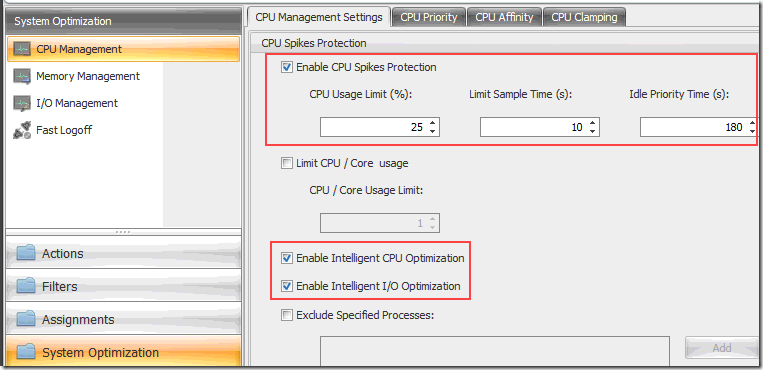
The System Optimization tab houses the resource control options, starting with CPU, provides high level to more granular controls. At a very basic level, CPU spike protection is intended to ensure that no process, unless excluded, will exceed the % limits you specify. Intelligent CPU and IO optimization, highlighted below, causes the agent to keep a list of processes that trigger spike protection. Repeat offenders are assigned a lower CPU priority at process launch. That is the key part of what this solution does: offending processes will have their base priority adjusted so other process can use CPU.

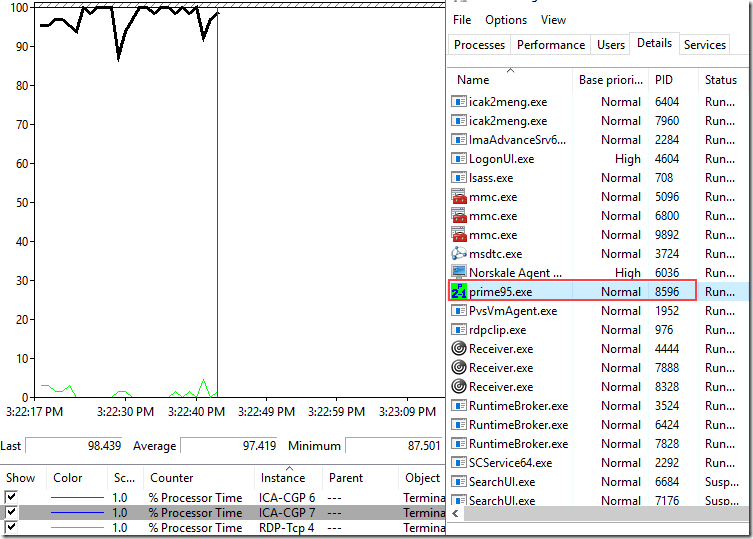
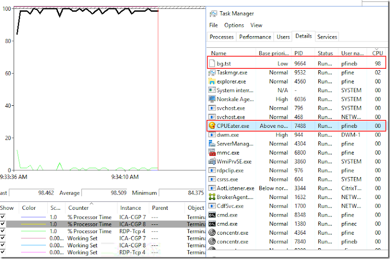
To show this in action, I ran Prime95 in one of my XenApp sessions. As you can see below the Prime95 process is running with a normal base priority and happily taking 100% of available CPU.

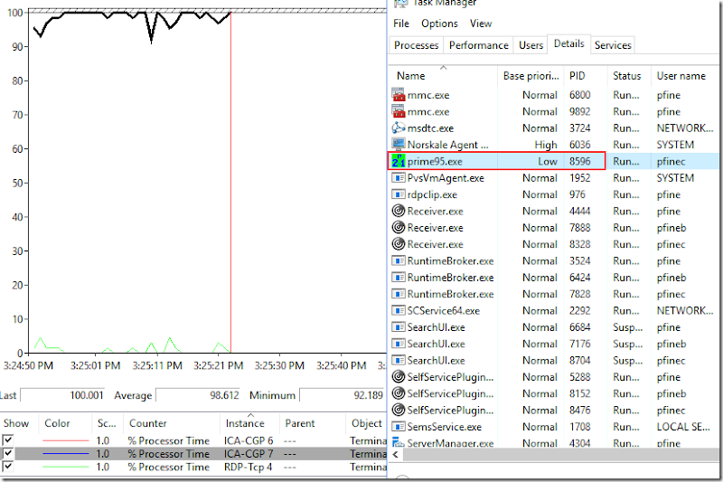
Once CPU Spike protection is enabled, notice the prime95 process has been changed to a Low priority but it isn’t actually limited to 25% according to my settings. What this appears to do in reality, is make problem processes less important so that others can take CPU time if needed, but no hard limit seems to be actually enforced. I tried a number of scenarios here including process clamping, varying %, optimized vs non, all in attempts to force Prime95 to a specific % of CPU utilization. I was unsuccessful. CPU utilization never drops, other processes are allowed to execute and share the CPU, but this would happen normally with DFSS.

I also tried using the CPU Eater process Citrix uses in their videos thinking maybe Prime95 was just problematic, but if you notice even in their videos, it does not appear that the policy ever really limits CPU utilization. The base priority definitely changes so that part works, but “spike optimization” does not appear to work at all. I’d be happy to be proven wrong on this if anyone has this working correctly.

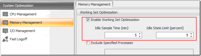
For memory optimization, WEM offers “working set optimization” which will reduce the memory working set of particular processes once the specified idle time has elapsed. Following the Citrix recommendation, I set the following policy of 5 minutes/ 5%.

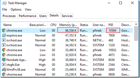
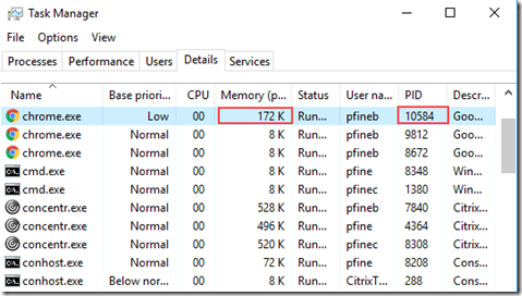
To test this, I opened a PDF in Chrome and waited for optimization to kick in. It works! The first image shows the Chrome process with the PDF first opened, the second image shows the process after optimization has worked its magic. This is a 99% working set memory reduction, which is pretty cool.


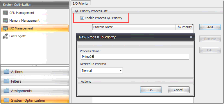
The IO Management feature allows the priorities of specific processes to be adjusted as desired, but not specifically limited by IO.

What about Citrix XenApp in Azure?

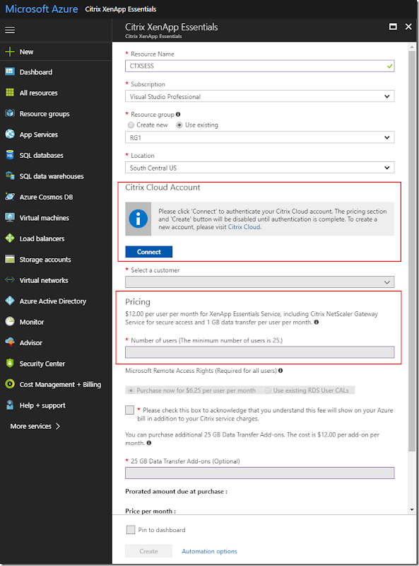
XenApp can also be run in Microsoft Azure via the Citrix XenApp Essentials offer. After the requisite Azure and Citrix Cloud subscriptions are established, the necessary XenApp infrastructure is easily created from the Compute catalog directly in Azure. The minimum number of users is 25 but your existing RDS CALs can be reused and Citrix billing is consolidated on your Azure bill for ease. Azure provides a number of global methods to create, scale, automate and monitor your environment. But at the end of the day, we are still dealing with Windows Server VMs, RDSH and Citrix Software. All the methods and rules discussed previously still apply, with one important exclusion: Citrix WEM is not available in Azure/ Citrix Cloud, so DFSS is your best bet unless you turn to supported third-party softs.

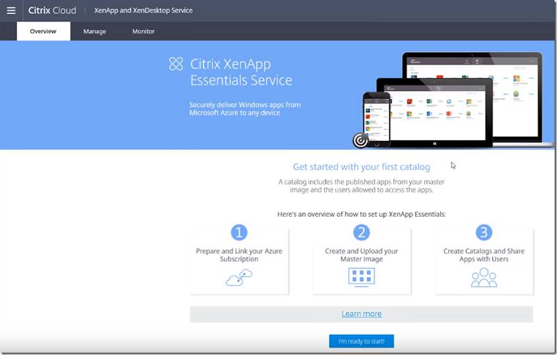
Once the XenApp infrastructure is deployed within Azure, the Citrix Cloud portal is then used to manage catalogs, resource publishing and entitlements.

What about VMware?

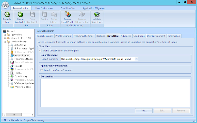
VMware also provides a number of methods to deploy and manage applications, namely: ThinApp, AirWatch and App Volumes while providing full integration support for Microsoft RDSH via Horizon or Horizon Apps.  For those keeping count, that’s FOUR distinct methods to deploy applications within Horizon. Similar to Citrix, VMware has their own UEM tool called… VMware UEM.  But unlike Citrix, the VMware UEM tool can only be used for user and application management, not resource management.

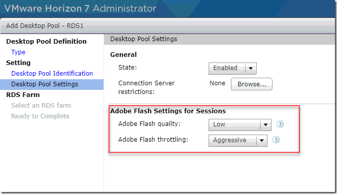
While Horizon doesn’t provide any RDSH resource-optimizing capabilities directly, there are a few settings to help reduce resource intensive activities such as Adobe Flash throttling which will become less compelling as the world slowly rids itself of Flash entirely.

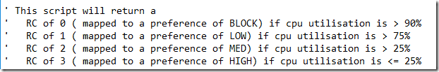
Something else VMware uses on RDSH hosts within a Horizon environment is memory and CPU loading scripts. These VBscripts live within C:\Program Files\VMware\VMware View\Agent\scripts and are used to generate Load Preference values that get communicated back to the Connection Servers. The reported value is then used to determine which RDSH hosts will be used for new session connections. If CPU or memory utilization is already high on a given RDSH host, VCS will send a new connection to a host with a lower reported load.

What about VMware Horizon in Azure?

VMware Horizon is also available in Azure via Horizon Cloud and has a similar basic architecture to the Citrix offer. Horizon Cloud acts as the control plane and provides the ability to automate the creation and management of resources within Azure. VMware has gone out of their way to make this as seamless as possible, providing the ability to integrate multi-cloud and local deployments all within the Horizon Cloud control plane, thus minimizing your need to touch external cloud services. From within this construct you can deploy applications, RDSH sessions or desktop VMs.

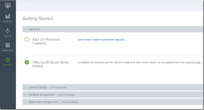
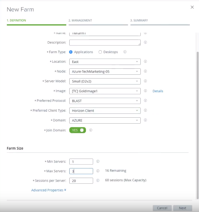
Horizon Cloud, once linked with Azure, provides full customized deployment options for RDSH farms that support delivery of applications or full session desktops. Notice that when creating a new farm, you are provided an option to limit the number of sessions per RDSH server. This is about it from a resource control perspective for this offer.


What about third party options?

Ivanti has become the primary consolidation point for predominant EUC-related tooling, most recently and namely, RES Software and AppSense. The Ivanti Performance Manager (IPM) tool (formerly AppSense Performance Manager) appears to be the most robust resource manager on the market today and has been for a very long time. IPM can be used not only for granular CPU/ memory throttling on RDSH but any platform including physical PCs or VDI desktops. I didn’t have access to IPM to demo here, so the images below are included from Ivanti.com for reference.

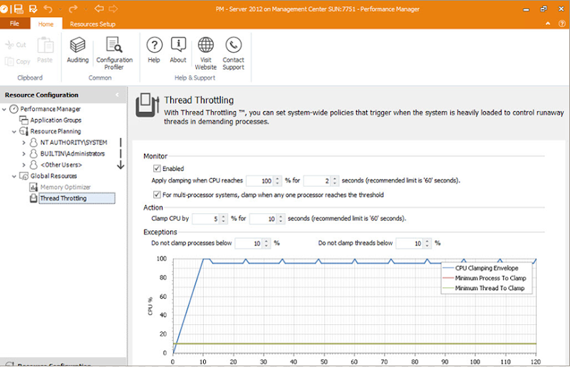
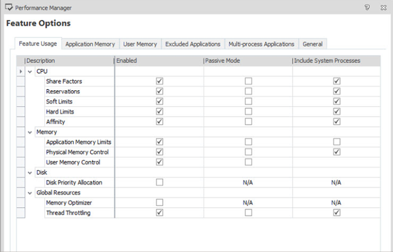
IPM provides a number of controls for CPU, memory and disk that can be applied to applications or groups, including those that spawn multiple chained processes with a number of options to dial in the desired end state. Performance Manager has been a favorite for RDSH and XenApp environments for the better part of a decade and for good reason it seems.

Resources

Citrix WEM product documentation: https://docs.citrix.com/en-us/workspace-environment-management/current-release.html
A year of field experience with Citrix WEM: https://youtu.be/tFoacrvKOw8
Citrix XenApp Essentials start to finish: https://youtu.be/5R-yZcDJztc
Horizon Cloud & Azure: https://youtu.be/fuyzBuzNWnQ
Horizon Cloud Requirements: http://www.vmware.com/info?id=1434
Ivanti Performance Manager product guide: https://help.ivanti.com/ap/help/en_US/pm/10.1/Ivanti%20Performance%20Manager%2010.1%20FR4%20Product%20Guide.pdf

The Native MSFT Stack: S2D & RDS – Part 3

Part 1: Intro and Architecture
Part 2: Prep & Configuration
Part 3: Performance & Troubleshooting (you are here)
Make sure to check out my series on RDS in Server 2016 for more detailed information on designing and deploying RDSH or RDVH.

Performance

This section will give an idea of disk activity and performance given this specific configuration as it relates to S2D and RDS.
Here is the 3-way mirror in action during the collection provisioning activity, 3 data copies, 1 per host, all hosts are active, as expected:

Real-time disk and RDMA stats during collection provisioning:

RDS provisioning isn’t the speediest solution in the world by default as it creates VMs one by one. But it’s fairly predictable at 1 VM per minute, so plan accordingly.

Optionally, you can adjust the concurrency level to adjust the number of VMs RDS can create in parallel by using the Set-RDVirtualDesktopConcurrency CMDlet. Server 2012R2 supported a max of 20 concurrent operations but make sure the infrastructure can handle whatever you set here.

Set-RDVirtualDesktopConcurrency –ConnectionBroker “RDCB name” –ConcurrencyFactor 20

To illustrate the capacity impact of 3-way mirroring, take my lab configuration which provides my 3-node cluster with 14TB of total capacity, each node contributing 4.6TB. I have 3 volumes fixed provisioned totaling 4TB with just under 2TB remaining. The math here is that of my raw capacity, 30% is usable, as expected. This equation gets better at larger scales, starting with 4 nodes, so keep this in mind when building your deployment.

Here is the disk performance view from one of the Win10 VMs within the pool (VDI-23) running Crystal DiskMark, which runs Diskspd commands behind the scenes. Read IOPS are respectable at an observed max of 25K during the sequential test.

image_thumb[3]

Write IOPS are also respectable at a max observed of nearly 18K during the Sequential test.

image_thumb[4]

Writing to the same volume, running the same benchmark but from the host itself, I saw some wildly differing results. Similar bandwidth numbers but poorer showing on most tests for some reason. One run yielded some staggering numbers on the random 4K tests which I was unable to reproduce reliably.

image_thumb[5]

Running Diskspd tells a slightly different story with more real-world inputs specific to VDI: write intensive. Here given the punishing workload, we see impressive disk performance numbers and almost 0 latency. The following results were generated from a run generating a 500MB file, 4K blocks weighted at 70% random writes using 4 threads with cache enabled.

Diskspd.exe -b4k -d60 -L -o2 -t4 -r -w70 -c500M c:\ClusterStorage\Volume1\RDSH\io.dat
image_thumb[6]

Just for comparison, here is another run with cache disabled. As expected, not so impressive.

image_thumb[8]

Troubleshooting

Here are a few things to watch out for along the way.
When deploying your desktop collection, if you get an error about a node not having a virtual switch configured:

One possible cause is that the default SETSwitch was not configured for RDMA on that particular host. Confirm and then enable per the steps above using Enable-NetAdapterRDMA.

On the topic of VM creation within the cluster, here is something kooky to watch out for. If working on one of your cluster nodes locally and you try to add a new VM to be hosted on a different node, you may have trouble. When you get to the OS install portion where the UI offers to attach an ISO to boot from. If you point to an ISO sitting on a network share, you may get the following error: Failing to add the DVD device due to lack of permissions to open attachment.

You will also be denied if you try to access any of the local paths such as desktop or downloads.

The reason for this is that the dialog is using the remote browser for file access on the server you are creating the VM. Counter-intuitive perhaps but the work around is to either log into the host where the VM is to be created directly or copy your ISO local to that host. 

Watch this space, more to come…

Part 1: Intro and Architecture
Part 2: Prep & Configuration
Part 3: Performance & Troubleshooting (you are here)

Resources

S2D in Server 2016
S2D Overview
Working with volumes in S2D
Cache in S2D

The Native MSFT Stack: S2D & RDS – Part 2

Part 1: Intro and Architecture
Part 2: Prep & Configuration (you are here)
Part 3: Performance & Troubleshooting
Make sure to check out my series on RDS in Server 2016 for more detailed information on designing and deploying RDSH or RDVH.

Prep

The number 1 rule of clustering with Microsoft is homogeneity. All nodes within a cluster must have identical hardware and patch levels. This is very important. The first step is to check all disks installed to participate in the storage pool, bring all online and initialize. This can be done via PoSH or UI.

Once initialized, confirm that all disks can pool:

Get-PhysicalDisk -CanPool $true | sort model

Install Hyper-V and Failover Clustering on all nodes:

Install-WindowsFeature -name Hyper-V, Failover-Clustering -IncludeManagementTools -ComputerName InsertName -Restart

Run cluster validation, note this command does not exist until the Failover Clustering feature has been installed. Replace portions in red with your custom inputs. Hardware configuration and patch level should be identical between nodes or you will be warned in this report.

Test-Cluster -Node node1, node2, etc -include "Storage Spaces Direct", Inventory, Network, "System Configuration"

The report will be stored in c:\users\\AppData\Local\Temp

Networking & Cluster Configuration

We’ll be running the new Switch Embedded Team (SET) vSwitch feature, new for Hyper-V in Server 2016.

Repeat the following steps on all nodes in your cluster. First, I recommend renaming the interfaces you plan to use for S2D to something easy and meaningful. I’m running Mellanox cards so called mine Mell1 and Mell2. There should be no NIC teaming applied at this point!

Configure the QoS policy, first enable the datacenter bridging (DCB) feature which will allow us to prioritize certain services the traverse the Ethernet.

Install-WindowsFeature -Name Data-Center-Bridging

Create a new policy for SMB Direct with a priority value of 3 which marks this service as “critical” per the 802.1p standard:

New-NetQosPolicy "SMBDirect" -NetDirectPortMatchCondition 445 -PriorityValue8021Action 3

Allocate at least 30% of the available bandwidth to SMB for the S2D solution:

New-NetQosTrafficClass "SMBDirect" -Priority 3 -BandwidthPercentage 30 -Algorithm ETS

Create the SET switch using the adapter names you specified previously. Items in red should match your choices or naming standards. Note that this SETSwitch is ultimately a vNIC and can receive an IP address itself:

New-VMSwitch -Name SETSwitch -NetAdapterName "Mell1","Mell2" -EnableEmbeddedTeaming $true

Add host vNICs to the SET switch you just created, these will be used by the management OS. Items in red should match your choices or naming standards. Assign static IPs to these vNICs as required as these interfaces are where RDMA will be enabled.

Add-VMNetworkAdapter –SwitchName SETSwitch –name SMB_1 –managementOS
Add-VMNetworkAdapter –SwitchName SETSwitch –name SMB_2 –managementOS

Once created, the new virtual interface will be visible in the network adapter list by running get-netadapter.

image_thumb

Optional: Configure VLANs for the new vNICs which can be the same or different but IP them uniquely. If you don’t intend to tag VLANs in your cluster or have a flat network with one subnet, skip this step.

Set-VMNetworkAdapterVLAN –VMNetworkAdapterName “SMB_1” –VlanId 00 –Access –ManagementOS
Set-VMNetworkAdapterVLAN –VMNetworkAdapterName “SMB_2” –VlanId 00 –Access –ManagementOS

Verify your VLANs and vNICs are correct. Notice mine are all untagged since this demo is in a flat network.

Get-VMNetworkAdapterVlan –ManagementOS
image_thumb1

Restart each vNIC to activate the VLAN assignment.

Restart-NetAdapter “vEthernet (SMB_1)”
Restart-NetAdapter “vEthernet (SMB_2)”

Enable RDMA on each vNIC.

Enable-NetAdapterRDMA “vEthernet (SMB_1)”, “vEthernet (SMB_2)”

Next each vNIC should be tied directly to a preferential physical interface within the SET switch. In this example we have 2 vNICs and 2 physical NICs for a 1:1 mapping. Important to note: Although this operation essentially designates a vNIC assignment to a preferential pNIC, should the assigned pNIC fail, the SET switch will still load balance vNIC traffic across the surviving pNICs. It may not be immediately obvious that this is the resulting and expected behavior.

Set-VMNetworkAdapterTeamMapping -VMNetworkAdapterName "SMB_1" -ManagementOS –PhysicalNetAdapterName “Mell1”
Set-VMNetworkAdapterTeamMapping -VMNetworkAdapterName "SMB_2" -ManagementOS –PhysicalNetAdapterName “Mell2”

To quickly prove this, I have my vNIC “SMB_1” preferentially tied to the pNIC “Mell1”. SMB_1 has the IP address 10.50.88.82

image_thumb3

Notice that even though I have manually disabled Mell1, the IP still responds to a ping from another host as SMB_1’s traffic is temporarily traversing Mell2:

image_thumb4

Verify the RDMA capabilities of the new vNICs and associated physical interfaces. RDMA Capable should read true.

Get-SMBClientNetworkInterface
image_thumb2

Build the cluster with a dedicated IP and slash subnet mask. This command will default to /24 but still might fail unless explicitly specified.

New-Cluster -name "Cluster Name" -Node Node1, Node2, etc -StaticAddress 0.0.0.0/24

Checking the report output stored in c:\windows\cluster\reports\, it flagged not having a suitable disk witness. This will auto-resolve later once the cluster is up.

The cluster will come up with no disks claimed and if there is any prior formatting, they must first be wiped and prepared. In PowerShell ISE, run the following script, enter your cluster name in the red text.

icm (Get-Cluster -Name S2DCluster | Get-ClusterNode) {
Update-StorageProviderCache


Get-StoragePool | ? IsPrimordial -eq $false | Set-StoragePool -IsReadOnly:$false -ErrorAction SilentlyContinue


Get-StoragePool | ? IsPrimordial -eq $false | Get-VirtualDisk | Remove-VirtualDisk -Confirm:$false -ErrorAction SilentlyContinue


Get-StoragePool | ? IsPrimordial -eq $false | Remove-StoragePool -Confirm:$false -ErrorAction SilentlyContinue


Get-PhysicalDisk | Reset-PhysicalDisk -ErrorAction SilentlyContinue


Get-Disk | ? Number -ne $null | ? IsBoot -ne $true | ? IsSystem -ne $true | ? PartitionStyle -ne RAW | % {


$_ | Set-Disk -isoffline:$false


$_ | Set-Disk -isreadonly:$false


$_ | Clear-Disk -RemoveData -RemoveOEM -Confirm:$false


$_ | Set-Disk -isreadonly:$true


$_ | Set-Disk -isoffline:$true


}


Get-Disk |? Number -ne $null |? IsBoot -ne $true |? IsSystem -ne $true |? PartitionStyle -eq RAW | Group -NoElement -Property FriendlyName


} | Sort -Property PsComputerName,Count

Once successfully completed, you will see an output with all nodes and all disk types accounted for.

Finally, it’s time to enable S2D. Run the following command and select “yes to all” when prompted. Make sure to use your cluster name in red.

Enable-ClusterStorageSpacesDirect –CimSession S2DCluster

Storage Configuration

Once S2D is successfully enabled, there will be a new storage pool created and visible within Failover Cluster Manager. The next step is to create volumes within this pool. S2D will make some resiliency choices for you depending on how many nodes are in your cluster. 2 nodes = 2-way mirroring, 3 nodes = 3-way mirroring, if you have 4 or more nodes you can specify mirror or parity. When using a hybrid configuration of 2 disk types (HDD and SSD), the volumes reside within the HDDs as the SSDs simply provide caching for reads and writes. In an all-flash configuration only the writes are cached. Cache drive bindings are automatic and will adjust based on the number of each disk type in place. In my case, I have 4 SSDs + 5 HDDs per host. This will net a 1:1 cache:capacity map for 3 pairs of disks and a 1:2 ratio for the last 3. Microsoft’s recommendation is to make the number of cache drives a multiple of the number of capacity drives, for simple symmetry. If a host experiences a cache drive failure, the cache to capacity mapping will readjust to heal. This is why a minimum of 2 cache drives per host are recommended.

Volumes can be created using PowerShell or Failover Cluster Manager by selecting the “new disk” option. This one simple PowerShell command does three things: creates the virtual disk, places a new volume on it and makes it a cluster shared volume. For PowerShell the syntax is as follows:

New-Volume –FriendlyName “Volume Name” –FileSystem CSVFS_ReFS –StoragePoolFriendlyName S2D* –size xTB

CSVFS_ReFS is recommended but CSVFS_NTFS may also be used. Once created these disks will be visible under the Disks selection within Failover Cluster Manager. Disk creation within the GUI is a much longer process but gives meaningful information along the way, such as showing that these disks are created using the capacity media (HDD) and that the 3-server default 3-way mirror is being used.

The UI also shows us the remaining pool capacity and that storage tiering is enabled.

Once the virtual disk is created, next we need to create a volume within using another wizard.  Select the vDisk created in the last step:

Storage tiering dictates that the volume size must match the size of the vDisk:

Skip the assignment of a drive letter, assign a label if you desire, confirm and create.


The final step is to add this new disk to a Cluster Shared Volume via Failover Cluster Manager. You’ll notice that the owner node will be automatically assigned:

Repeat this process to create as many volumes as required.

RDS Deployment

image_thumb[1]

Install the RDS roles and features required and build a collection. See this post for more information on RDS installation and configuration. There is nothing terribly special that changes this process for a S2D cluster. As far as RDS is concerned, this is an ordinary Failover Cluster with Cluster Shared Volumes. The fact that RDS is running on S2D and “HCI” is truly inconsequential.
As long as the RDVH or RDSH roles are properly installed and enabled within the RDS deployment, the RDCB will be able to deploy and broker connections to them. One of the most important configuration items is ensuring that all servers, virtual and physical, that participate in your RDS deployment, are listed in the Servers tab. RDS is reliant on Server Manager and Server Manager has to know who the players are. This is how you tell it.

To use the S2D volumes for RDS, point your VM deployments at the proper CSVs within the C:\ClusterStorage paths. When building your collection, make sure to have the target folder already created within the CSV or collection creation will fail. Per the example below, the folder “Pooled1” needed to be manually created prior to collection creation.

During provisioning, you can select a specific balance of VMs to be deployed the RDVH-enabled hosts you select, as can be seen below.

RDS is cluster aware in that the VMs it creates can be created as HA within the cluster and the RD Connection Broker (RDCB) remains aware as to which host is running which VMs should they move. In the event of a failure, VMs will be moved to a surviving host by the cluster service and the RDCB will keep track.

Part 1: Intro and Architecture
Part 2: Prep & Configuration (you are here)
Part 3: Performance & Troubleshooting

Resources

S2D in Server 2016
S2D Overview
Working with volumes in S2D
Cache in S2D

Native RDS in Server2016 – Part 4 – Scaling & HA

Part 1: The Basics
Part 2: RDVH
Part 3: RDSH
Part 4: Scaling and HA (you are here)

Most environments that I’ve run across using native RDS for VDI (RDVH) tend to be fairly small, <500 seats but I have seen some larger footprints built around RDSH. The single largest problem for the native RDS solution is management of the environment. This tends to get pretty unwieldy from a management perspective around the 500 user mark using native tools. PowerShell can and should be used in larger environments. The RD Connection Broker (RDCB) itself is capable of 10K concurrent connections so clearly supports scale in and of itself, but it's really unfortunate that the surrounding native management tool stack isn't up to the task and there really isn't much to enable it either. Unidesk can be leveraged to extend the native RDS story (currently Server 2012 R2) providing much better manageability by integrating directly with the RDCB to create desktops and collections. Unidesk provides a good solution that fundamentally alters the deployed architecture using a highly scalable and robust layering model.
The other big consideration with scaling the native RDS stack is MAC address management in Hyper-V. This one is important, especially with compute host densities ever climbing as the semiconductors pump out increasingly core-dense CPUs. By default, Hyper-V supports 256 unique MACs per host. Every Hyper-V host in the world has a 3-octet prefix of 00-15-5D, the next two octets are unique to each host and derived from the IP address assignment, the last octet is auto-generated between 00-FF. The last octet alone is an 8-bit value so represents 256 possible MAC address. You can modify the 4th or 5th octets to increase the pool on a per host basis but be very careful that you don’t accidentally assign an overlapping value. In other words, don’t mess with this unless you really know what you’re doing. Another scenario to avoid is MAC address pool conflicts,  which would potentially happen if you deploy a Hyper-V host with a dynamic IP that could be leased to another new Hyper-V server at some point. Very important lesson here is to use static IPs for your Hyper-V hosts.

What about SCVMM?

This question usually comes up in relation to RDS, do you need System Center Virtual Machine Manager (SCVMM), can you use SCVMM, how does it integrate? The Citrix XenDesktop solution requires SCVMM as a component of that architecture for VM provisioning but not so for RDS. In the case of RDS, VMM not only is not required at all but there really isn’t a very direct integration path between the products. SCVMM here should be seen as an external management tool to compliment the base set of tools used to manage your Hyper-V Failover Clusters, storage and VMs. So what can you do with VMM in an RDS deployment?
SCVMM can be used as a basic deployment enabler of the environment or a provisioning/ mgmt tool for unmanaged collections, but does not integrate directly with the RDS farm or the RDCB. This means that SCVMM cannot be used to provision any VM intended to exist within a managed pool owned by the RDCB. You can use SCVMM to create VMs for an unmanaged collection or deploy your RDSH VMs while also benefitted from using a much larger pool to manage assignable MAC addresses without worry of conflict or shortage.
To fully appreciate what is possible here it is important to understand the concept of unmanaged and managed collections in RDS. Managed collections are pools that the RDCB creates and maintains using a template VM, including the ability to recreate VMs as needed. Unmanaged collections are pools to which the RDCB brokers connections, but there is no template VM therefore you have to create and manage the pool manually. Everything I’ve shown so far in this series has been “managed” which is the most common deployment style due to ease of ongoing maintenance. If you want to use SCVMM to manage your desktop pool VMs and take advantage of features like Intelligent Placement and a massive MAC address pool, then you will need to use an unmanaged collection. This model is best suited for a 1:1 persistent desktop deployment and as you can see below, can still make use of UPDs.
For example, in this deployment I have SCVMM 2016 running SQL Server 2014 on a dedicated Server 2016 VM. I wish to deploy and manage a large RDS pool of persistent desktops using SCVMM. The first step is to create an unmanaged collection. This is specified during the creation of the collection by unchecking the “Automatically create and manage virtual desktops” option. Select any additionally desired options and deploy.

Once the collection is created, clone however many VMs required using SCVMM via PowerShell and spread them across the cluster using SCVMM’s Intelligent Placement feature. There is no way in the SCVMM GUI to clone multiple VMs so this operation is scripted, see Resources at the bottom. This method eliminates the concerns about too few or overlapping MAC addresses and balances the VMs across the cluster automatically based upon available capacity. Once the VMs are created, they then need to be manually added to the new unmanaged collection. This can be done using PowerShell or Server Manager. Once this has been done users will be able to see the collection in RD Web Access and the RDCB will be able to broker user connections to the pool. Thousands of VMs could be deployed this way and brokered using RDCB.

Add-RDVirtualDesktopToCollection -CollectionName Name -VirtualDesktopName Clone1 -ConnectionBroker RDCB.domain.com

Alternatively, VMs can be added to the unmanaged pool using Server Manager.

But wait, can’t I manually add existing VMs to a managed collection too? Nope! You can add additional VMs to a managed collection but they must be based on the template already assigned to the collection thus ensuring consistency.

Service Templates
The other use case for SCVMM in the RDS context is for deployment and scaling of the surrounding infrastructure using Service Templates. Within SCVMM, one can create a Service Template to deploy entire or individual pieces of an RDS deployment. The Service Template element within SCVMM provides a visual method to build a master script that is used to provision management server VMs using a specific hardware configuration, with specific applications installed, in a specified order of execution. The possibilities here are nearly limitless as you can have at your disposal the full capability of any application, PowerShell or script. Lock down your Service Templates and you could build, rebuild or expand any deployment with the push of a button.

Scaling for Compute

I’ll talk about HA next which inherently brings scalability to the management stack but first, consider compute as part of the architecture. Compute in this context refers to the physical Hyper-V hosts that provide resources for desktop or RDSH VMs, exclusively. The limitations of the compute layer will almost always be based on CPU. It is the one finitely exhaustible resource not easily expanded unless you upgrade the parts. Adjusting resources to provide additional IO, memory or network throughput is a straight-forward process linearly scalable via the capabilities of the server platform. To get the best bang for the buck, most customers seek to deploy the highest reasonable number of users per compute host possible. Hyper-V provides a great deal of CPU efficiency at the expense of slightly higher IO. Depending on the workload and VM profile, one could expect to see 5-10+ VMs per core in an RDS deployment. Compute hosts used for RDSH VMs will require few total VMs per physical host but have the potential to host a much larger number of total users. NUMA architecture alignment is important to ensure maximum performance in these scenarios. A higher number of cores per CPU is generally more important than the clock speed. Considering that it is easy to achieve 256 VMs on a single compute host (default MAC address limit provided by Hyper-V), the appropriate host hardware mix should be selected to ensure the maximum performance and end user experience. Compute hosts can be added to a deployment in block fashion to satisfy a total desired number of users. Keep in mind the nuances of managing a native RDS stack at scale and whether or not it may make sense to invest in 3rd party solutions to bolster your deployment.

Solution High Availability

High-availability can be configured for this solution in a number of different areas. The general principles of N+1 apply at all service levels including physical components. The following guidance will provide a fully redundant RDS infrastructure:

  • Add Top of Rack switching infrastructure for physical port redundancy
  • Add Hyper-V compute and mgmt hosts for failover
    • Hyper-V hosts configured in a failover cluster to protect physical compute resources also using Cluster Shared Volumes to protect storage (ideally cluster mgmt and compute separately)
  • Add load balancers to manage SSL offload and HTTPS connections from clients for RD Gateways and RD Web Access servers
  • Add additional RD Gateway and RD Web Access servers to provide resiliency and redundancy
  • Add additional RDCB servers configured to connect to a clustered SQL Server instance
  • Add a 2nd license server VM configured with temporary licenses, deploy both via GPO but list the primary instance first. Should the primary fail, the secondary will serve the environment using temporary entitlements until the primary is restored.
  • Cluster your file server or add a clustered NAS head back-ended by redundant shared storage for UPDs and user data

Here is another look at the larger architecture but within the context of providing HA:

RDCB HA

The RD Broker itself is the most single important role that needs special consideration and configuration to make it HA. Configuring HA for the RDCB creates a cluster with a DNS name assigned for load balancing that keeps track of the location and assignments of user sessions and desktops. First, create a new database on your SQL server with the RDCB server configured to have dbcreator permissions.

With SQL setup, install the SQL Native Client on all RDCB servers and launch the Configure High Availability wizard from the Deployment Overview.

Choose shared SQL mode, name the clustered RDCB instance and provide the SQL connection string in the following format.

DRIVER=SQL Server Native Client 11.0;SERVER=VMM16.dvs.com; Trusted_Connection=Yes;APP=Remote Desktop Services Connection Broker;DATABASE=RDSQL;
         

Once successfully completed, the RDCB will show as HA mode in the Deployment Overview and additional brokers can be added using the same dialog.

RDSH HA

An RDSH collection can be scaled or made HA by adding additional RDSH VMs. Once your new RDSH VMs are created and have the appropriate applications installed, they must be added to the “All Servers” management pool within Server Manager.

Once all hosts or VMs are added to the server management pool, you can add the new VMs to your existing RDS deployment.

After additional RDSH servers are added to the overall RDS deployment, they can then be added to a specific session collection from the Host Servers dialog of the collection management page.

Once successfully added to the collection, all added server instances will be visible and available to accept connections.

Load balancing between multiple RDSH instances can be configured from within the collection properties dialog to ensure equal distribution or bias, if desired. Making a server “heavier” via relative weight will cause the Connection Broker to push more connections to it accordingly.

RDWA HA

Additional RD Web Access servers can be added at any time from the Deployment Overview or Deployment Servers dialogs. Select the new server instance you wish to add, confirm and deploy. As always, make sure this server instance is added to the “All Servers” management pool. Behind the scenes IIS is configured on each selected instance to host the website and feed for RDweb.

Once deployed, you should see the new RDWA instance(s) in the RDS Deployment Properties accessible from the RDS Overview page.

Any Collection made to be visible in RD Web Access will be accessible from any RDWA instance. RDWA instances can be accessed directly via URL, load balanced with DNS or put behind a hardware or software load balancer (F5/ Netscaler).

RD Licensing

RD Licensing is one of the trickier roles to make HA as there is no easily exploitable native method to accomplish this. This is generally true regardless of broker solution selected in this space. There are a couple viable methods that require manual intervention that can be used to protect the RD License role. The first method requires two VMs each configured with the RD Licensing role, hosted on separate physical hosts. The first instance has the purchased licenses installed and validated by the Microsoft Clearing House. The second VM is configured with temporary licenses. Both instances are configured via GPO for users but the server with the validated licenses is on the top of the list. Should the primary fail, users can still connect to the environment using temporary licenses until the primary is back online.
The other method also involves two VMs. The primary VM is configured with purchased licenses installed and validated by the Microsoft Clearing House. The VM is cloned, shut down and moved to a separate physical host. Should the primary instance fail for whatever reason, the cold standby can then be powered on to resume the role of the primary. The caveat to this method is that if anything changes from a licensing perspective, the copy to cold stand-by clone process needs to be repeated.

RD Gateway

To optimize and secure connections to the RDS farm from untrusted locations (the interwebs), RDGW can be used and made HA. RDGW terminates SSL for remotely connecting clients, one tunnel for incoming data one for outgoing. UDP can also be utilized for optimized transport of data over WANs using the HTTP transport.  RDGW is installed like any other RDS role and includes IIS as a requisite part of the install. RD Gateway Manager is used to manage the configuration and policies of the gateway including SSL certs and transport settings that provide the ability to change HTTP/UDP listeners. RDGW can also use RD Connection Authorization Policies (RD-CAP) which can be stored locally on the RDGW installed or managed centrally on an NPS server. RDGW can be load balanced as a regular HTTP web service including the offloading of SSL termination. DNS Round Robin is not supported and cannot be used in this scenario.

Failover Clustering and RDS

Lastly, a quick point on the role of Failover Clustering in RDS environments. Failover Clustering is recommended to provide HA for the Hyper-V environment and component level protection of the RDS deployment. Should a node fail or require maintenance in a Failover Cluster, it’s VMs will be restarted or evacuated to another node with available capacity. RDS is cluster aware in that it remains aware of the location of VMs within a Failover Cluster, including if they move around, but it does not integrate directly nor make direct use of the Failover Cluster. In this context the resources for the VMs themselves can be protected giving the management VMs a place to migrate or restart should a failure occur. Any storage added directly to the cluster should be converted to a Cluster Shared Volume enabling multiple simultaneous writers to each volume. RDS itself doesn’t care what the underlying storage is nor whether the environment is clustered or not. Remember that any provisioning activities you perform will address RDVH hosts directly with the RDCB providing the ability to select the number of VMs deployed on each host.

Part 1: The Basics
Part 2: RDVH
Part 3: RDSH
Part 4: Scaling and HA (you are here)

Resources

Creating Service Templates for RDS in SCVMM
Deploying multiple VMs from a template in SCVMM (PoSH)
Hyper-V Dynamic MAC addressing for RDS

Native RDS in Server2016 – Part 3 – RDSH

Part 1: The Basics

Part 2: RDVH

Part 3: RDSH (you are here)

Part 4: Scaling and HA

image[27]

In the first two parts of this series, we explored the basic constructs and architecture of RDS in Server 2016, how to create a farm and how to deploy virtual desktops. In this part we’ll look at integrating RDSH into this environment to provide published applications and shared sessions which compliment a virtual desktop deployment. Many actually start with RDSH or published apps as step 1 then move into virtual desktops to provide greater control or performance.

Looking at the overview page of your RDS deployment, you’ll notice the session host options are greyed out, this is because the deployment (farm) does not currently have these features installed.

image

To add RDSH hosts to an existing RDS deployment, you have to first modify the RDS deployment to enable session-based services. Once your RDSH VMs are created and running within Hyper-V, run the Add Roles and Features Wizard and choose session based deployment. You’re going to have deja vu here but remember, this is all to modify the existing deployment and this is the last time you should need to run this wizard. The wizard will check for the existence of a broker and web access roles which should already exist. Once you get to the RD Session Host part of the dialog, here is where you add your session hosts to the deployment and install the RDSH role on each. Select your target VMs, confirm and deploy. The VMs receiving the RDSH role will be restarted as part of this process.

image     image     image

Via PowerShell (change to your server names):

New-RDSessionDeployment -ConnectionBroker CBname.domain.com -WebAccessServer WAname.domain.com -SessionHost RDSHname.domain.com

Make sure the new servers are added to the Servers pool within Server Manager. At this point you will be able to create a new session collection from the overview page in Server Manager which will no long be greyed out. Give the collection a name, specify the server(s) you want to host the collection and add the user groups you wish to entitle.

image     image     image


Via PowerShell (change to your server names):

New-RDSessionCollection -CollectionName RDSH -SessionHost RDSH.domain.com -ConnectionBroker CBname.domain.com

If you want to use UPDs to persist user settings between sessions, configure the location and size of the UPDs, confirm you selections and deploy.

image

Keep in mind that UPD’s are collection-specific, they cannot be used in more than one collection.     

image

Via PowerShell (change to your server names):

Set-RDSessionCollectionConfiguration -CollectionName RDSH -ConnectionBroker CBname.domain.com -DiksPath C:\ClusterStorage\Volume1\RDSH_UPD -EnableUserProfileDisk -MaxUserProfileDiskSizeGB 1


RD Licensing

By default, RDS will offer a 120-day grace period for licensing, after which you will need to use an RD License server instance with a proper license to suit your licensing mode. The license server activity is a light weight role and can be safely combined with the RD Connection Broker role. From the Deployment Overview page on the main RDS screen, select Add RD Licensing Server. Choose your broker VM and confirm.

image

Edit the deployment properties of your RDS Deployment and choose the RD Licensing section. Select your desired licensing mode and RD License server.

image

To manage your RDS Cals, launch the RD Licensing Manager from the Server Manager Tools menu. Connect to your license server, right-click and select Activate. Complete the information forms and start the Install Licenses Wizard. The wizard will contact the Microsoft ClearingHouse real-time to authorize your server. Microsoft takes licensing of RDSH servers very seriously as there is a tremendous opportunity for software license abuse. Enter the particulars of your license agreement to activate your deployment.

image     image

Another useful tool is the RD Licensing Diagnoser which can help identify problems as well as help achieve compliance. This tool can be launched from the Tools/ Remote Desktop Services menu within Server Manager.

 image


Via PowerShell (change to your server names):

Add-RDServer -Server RDLicName.domain.com -Role RDS-Licensing -ConnectionBroker CBname.domain.com

Set-RDLicenseConfiguration -ConnectionBroker CBname.domain.com -LicenseServer RDLicName.domain.com -Mode PerUser


Managing the Collection

Once the collection is created it will become available for management in Server Manager. Entitlements, RD Web visibility, client settings and UPDs can be manipulated via the collection properties. Idle sessions can be force logged off while active sessions can be shadowed, disconnected, messaged or logged off. RemoteApp Programs provides application virtualization for programs running within the RDSH servers of the pool to RD Web Access. Session collections can offer full session desktops or published applications, but not both. Virtual GPU is not supported for session collections, you’ll need to look to Citrix XenApp for that.

image

Once the collection is created you can either publish specific applications or full shared sessions themselves. Individual applications will launch seamlessly and can even be tied to specific file extensions. If you wish to publish a full shared session desktop, this is very easy to do. Simply edit the properties of the collection via the Tasks dropdown on the collection page and ensure that the box is checked to “Show the session collection in RD Web Access.” This will provide an icon in RD Web that users can click to launch a full desktop experience on the RDSH server.

image

To publish specific applications, select “Publish RemoteApp Programs” from the tasks dropdown in the middle of the page. RDS will poll the RDSH servers currently part of your collection for available apps to publish. As the note at the bottom of the initial dialog says, make sure than any program you wish to publish is installed on all RDSH servers within the collection. Confirm your selections and publish.

image     image     image

Via PowerShell (use $variables and script for multiple apps or repeat command for each):

New-RDRemoteApp -CollectionName RDSH -DisplayName "OpenOffice Calc" -FilePath "%SYSTEMDRIVE%\Program Files (x86)\OpenOffice...scalc.exe" -ShowInWebAccess 1

Connecting to Resources

At this point, anything you have published and entitled will be available in RD Web Access. By default this URL as created within IIS will be https:///RDWeb and should be secured using a proper certificate.You can see below that I now have a mix of RDSH published apps, a RemoteApp Program from a desktop collection, a session collection, as well as a desktop collection. What users will see will vary based on their entitlements.  To enable direct connection to a collection using the Remote Desktop Connection (RDC), a collection within RD Web can be right clicked which will trigger a download of the .rdp file. This file can be published to users and used to connect directly without having to log into RD Web first.

image

Editing the .rdp file in a text editor will reveal the embedded characteristics of the connection which include the client settings, connection broker, gateway and most importantly the collection ID which in this case is “RDSH2”. 

image

RemoteApp Programs can also be delivered directly to a users’ Start menu by connecting the client session to the feed of the RD Web Access Server. This can be configured individually or delivered via GPO. A proper security certificate is required.

image

When a user initiates a connection to a resource with an unknown publisher for the first time they will be greeted with the following dialog. The resources allowed by the remote host can be restricted via deployment properties or GPOs. The RemoteApp will launch within a seamless session window and to the user will appear to be running locally.

image     image

At this point the connection broker does as the name implies and connects users to resources within the deployment while maintaining where VMs are running and which VMs users are logged in to. In the next section we’ll take a look at scaling and HA.

Part 1: The Basics

Part 2: RDVH

Part 3: RDSH (you are here)

Part 4: Scaling and HA

Resources:

RDS Cmdlets for Server 2016

Native RDS in Server2016 – Part 2 – RDVH

Part 1: The Basics
Part 2: RDVH (you are here)
Part 3: RDSH
Part 4: Scaling and HA

image[27]

In part 1 of this series we took a look at the over all architecture of RDS in Server 2016 along with the required components  contrasting the function performed by each. If you’re not new to RDS, things really haven’t changed a great deal from Server 2012R2 from a basic architecture perspective. In this chapter we’ll take a look at the RDVH role, what it does, how to get going and how to manage it.

Test Environment

Here is a quick rundown of my environment for this effort:

  • Servers – 2 x Dell PowerEdge R610’s, dual X5670 (2.93GHz) CPUs, 96GB RAM, 6 x SAS HDDs in RAID5 each
  • Storage – EqualLogic PS6100E
  • Network – 1Gb LAN, 1Gb iSCSI physically separated
  • Software – Windows Server 2016 TP5 build 14300.rs1
  • Features – Hyper-V, RDS, Failover Clustering

Installation

The first step is to create an RDS deployment within your environment. Consider this construct to exist as a farm that you will be able to install server roles and resources within. Once the initial RDS deployment is created, you can create and expand collections of resources. An RDS deployment is tied to RD Connection Broker(s) which ultimately constitute the farm and how it is managed. The farm itself does not exist as an explicitly addressable entity. My hosts are configured in a Failover Cluster which is somewhat inconsequential for this part of the series. I’ll explain the role clustering plays in part 4 but the primary benefits are being able to use Cluster Shared Volumes, Live Migration and provide service HA.
On one of your management hosts that already has Hyper-V enabled, fire up the Add Roles and Features Wizard, select Remote Desktop Services installation and choose your deployment model. “Standard” would be what is chosen most often here unless doing a POC then “Quick Start” may be more appropriate. MultiPoint is something entirely different which carries a different set of requirements. You don’t have to use this wizard but it is an easy way to get going. I’ll explain another way in a moment.

image     image 

Next choose whether you’ll be deploying desktop VMs or sessions. Desktops require the RDVH role on the parent, sessions require RDSH and can be enabled within Server VMs. For this portion we’ll be focusing on RDVH.

SNAGHTML463b08fe      image

Next select the hosts or VMs to install the RD Connection Broker and Web Access roles. For POCs everything on one host is ok, for production it is recommended to install these RDS roles onto dedicated Server VMs. You’ll notice that I pointed the wizard at my Failover Cluster which ultimately resolved to a single host (PFine16A).

image     image    

The third piece in this wizard is identifying the host(s) to assume the RDVH role. Remember that RDVH goes on the physical compute host with Hyper-V. Confirm your selections and deploy.

image     image

The installation will complete and affected hosts or VMs will be restarted. In order to manage your deployment, all Hyper-V hosts and server VM roles that exist within your deployment must be added to the Servers tab within Server Manager. This can be done at the very beginning as well, just make sure it gets done or you will have problems.
image

At this point your RDS deployment should be available for further configuration with the option to create additional roles or a desktop collection. Unless you are building a new RDS deployment, when adding additional server roles, it is much easier to select the role-based installation method from the Add Roles and Features Wizard and choose the piece-parts that you need. This is especially true if adding singular roles to dedicated server VMs. There is no need to rerun the “Remote Desktop Services Installation” wizard, in fact it may confuse things.
image

Desktop VM Templates and Collections

Before we create a new collection, we need to have a template VM prepared. This can be a desktop or server OS but the latter requires some additional configuration. By default, the connection broker looks for a desktop OS SKU when allowing a template VM to be provisioned. If you try to use a Server OS as your template you will receive the following error:
image[20]

To get around this, you must add the following registry key to any host that sources or owns the master template. Reboot and you will be allowed to use a Server OS as a collection template.

HKLM\System\CurrentControlSet\Services\VMHostAgent\Parameters\SkipVmSkuValidation   REG_DWORD     1

Your template should be a normal VM (Gen 1 or 2), fully patched, desired software installed and manually sysprepped. That’s right, RDS does not integrate the ability to auto-clone a template VM to new unique VMs, you need to do this manually as part of your collection prep.
image

Make sure whatever template you intend to provision in your desktop collection is already added to your RDVH host or cluster and powered off.
image[2]

Launch the Create Collection wizard within Server Manager, give the collection a name and select pooled or personal desktops.

image     image

Select the template VM to use to create the collection, if using a Server OS make sure you completed the steps above to make the template VM visible and selectable in the RD Collection wizard. Keep in mind that a template VM can only be used in a single collection, no sharing allowed. Provide an answer file if you have one or use the wizard to generate the settings for time zone and AD OU.
image     image     image

Specify the users to be entitled to this collection and the number of desktops you wish to deploy along with the desired naming convention. For allocation, you can now decide how many VMs of the total pool to provision to each available physical host. Take note of this, VMM is not here to manage Intelligent Placement for you, you can accept the defaults or decide how many VMs to provision to a host.

image     image

     
Select where to store the VMs: this can be a local or shared drive letter, SMB share or CSV. The ability to use CSVs is one of the benefits of using Failover Clustering for RDS deployments. Next, if you intend to use UPDs for storing user settings, specify the path and size you want to allocate to each user. Again, CSVs work fine here. Confirm and deploy.
image     image     image

Behind the scenes, RDS is making a replica of your template VM’s VHDX stored in the volume you specified, which it will then clone to the collection as new VMs.
image

The pooled VMs themselves are thin provisioned, snapped (checkpointed) and only consume a fraction of the storage consumed by the original template. When reverting back to a pristine state at log off, the checkpoint created during provisioning is applied and any changes to the desktop OS are discarded.
image

UPDs are ultimately VHDX files that get created for each user that connects to the collection. By default all user profile data is stored within a UPD. This can become unwieldy if your users make heavy use of the Desktop, Documents, Music, etc folders. You can optionally restrict which pieces should be stored within the UPD and use folder redirection for the others if desired.
image

When UPD is enabled for a collection, there is a template UPD created within the volume specified then each user gets a dedicated UPD with the SID of the user as the file name. Selected settings are saved within and follow the user to any session or desktop they log into within the collection. This file will grow up to the maximum allotted.
image

Managing the Collection

Depending on the speed of your hardware, your pooled VMs will deploy one by one and register with the broker. Once the collection is deployed it will become available for management in Server Manager. Entitlements, RD Web visibility, client settings and UPDs can be manipulated via the collection properties. Desktop VMs can be manipulated with a basic set of controls for power management, deletion and recomposition. RemoteApp Programs provides a way to publish applications running within the desktop pool to RD Web Access without requiring RDSH or RD Lics which may be useful in some scenarios. Virtual GPU can also be enabled within a desktop collection if the host is equipped with a supported graphics cards. Server 2016 adds huge improvements to the Virtual GPU stack.
image

Notice here that RDS is aware of which VMs are deployed to which hosts within my cluster. Should a VM move between physical hosts, RDS will see that too. When removing VMs from a collection, always do this from the Collections dialog within Server Manager as it’s a cleaner process. This will turn off the VM and remove it from Hyper-V. If you delete a VM from Hyper-V manager, the RDS broker will report that VM as unknown in Server Manager. You will then need to delete it again from within Server Manager.

image     image         

If you have an AD object that already exists with the same machine name, that VM will fail to provision. Make sure that if you redeploy any collection using the same names that AD is also cleaned up before you do so.
image

As is always the case when working with VMs in Hyper-V, manual file system cleanup is required. Deleting a VM from Hyper-V or RDS in Server Manager will not remove the files associated with the VM. You could always add them back if you made a mistake but otherwise you will need to manually delete or script an operation to do this for you.
image[17]

RemoteApp Programs can be used to publish applications for users of a desktop collection. This does not require RDSH but it will only allow a single user to connect to a published resource, just like a desktop VM. If you use RemoteApp Programs within a desktop collection, you will be unable to publish the desktop collection itself. For example, I have Google Chrome published from one desktop within my collection, this prevents the entire collection from being presented in RD Web Access only allowing the published app. To make this collection visible in RD Web Access again, I have to unpublish all RemoteApp Programs from the collection then select to show the collection in RD Web Access. The same is true of session collections. You can publish apps or you can publish sessions but not both simultaneously within a single collection.
image

Connecting to Resources

Logging into RD Web Access is the easiest way to access published resources. By default this URL as created within IIS will be https:///RDWeb and can be secured using a proper certificate. Depending on user entitlements, users will see published apps, sessions or desktops available for launching. To enable direct connection to a collection using the Remote Desktop Connection (RDC), a collection within RD Web can be right clicked which will trigger a download of the .rdp file. This file can be published to users and used to connect directly without having to log into RD Web first.
image

Editing the .rdp file in a text editor will reveal the embedded characteristics of the connection which include the client settings, connection broker, gateway and most importantly the collection ID which in this case is “RDC”. 
image

At this point the connection broker does as the name implies and connects users to resources within the deployment while maintaining where VMs are running and which VMs users are logged in to. In the next section we’ll take a look at integrating RDSH into this environment.

Part 1: The Basics
Part 2: RDVH (you are here)
Part 3: RDSH
Part 4: Scaling and HA

Native RDS in Server2016 – Part 1 – The Basics

Part 1: The Basics (you are here)
Part 2: RDVH
Part 3: RDSH
Part 4: Scaling and HA
image
As is the case with a number of Microsoft workload technologies, particularly in the End User Compute (EUC) space, Microsoft provides you with the basic tools to fulfill a particular requirement or use case. If you want to get more granular with management or fancier with features, your next step would be to invest into their partner ecosystem to expand upon the base offering. Such is and always has been the case with Remote Desktop Services (RDS). Remote Desktop Virtualization Host (RDVH) and Remote Desktop Session Host provide a very functional, but basic solution for virtual desktops or shared sessions. If you want greater granularity with an increased feature set while wanting to stay on Hyper-V, you can upgrade into the Citrix XenDesktop or XenApp product space. If you want to use vSphere as your hypervisor you could run RDSH VMs natively or add greater management granularity and features by buying into the VMware Horizon product space. At the end of the day, no matter which way you go, if you intend to deploy shared sessions or shared virtualized applications, as most environments do initially, Microsoft RDSH is the technology underneath it all. This series will cover the what, why and how of the native Microsoft RDS stack for Server 2016.

Use Cases

The first thing to decide is whether you need shared sessions/ published apps (most common) or dedicated pooled or personal virtual desktops assigned 1:1 to each user. RDSH is the most widely deployed technology in this space and where most environments initially invest to virtualize published applications or deploy a shared hosted workspace. If the shared session/ app solution falls short in any way or if users need greater dedicated performance, the next step is to isolate users via pooled or personal virtual desktops. Pooled desktops can be refreshed for each new user (non-persistent) while personal desktops are dedicated to a user (persistent). Pooled desktops or shared sessions can make use of User Profile Disks (UPD) which store user settings and folders in a central location. A collection can make use of both folder redirection as well as UPDs.
Virtual desktops are completely complimentary to published applications which can reduce the complexity of the template used for a collection while lowering the resource consumption of VMs running within. This is done by offloading the running applications to RDSH hosts keeping the desktop VMs leaner thereby yielding greater density per compute host. Multipoint is now an installable role in Server 2016 RDS which is useful for single-server multi-user scenarios not requiring RDP across the network. For Server 2016 all uses cases can be built on-premise, in the cloud, or a hybrid of the two. This blog series will focus on the on-premise variety which is also most common.

What’s new in RDS 2016

Personal Session Desktops – A new type of session collection that allows users to be assigned to a dedicated RDSH VM (Azure deployments)
Gen2 VMs – Full support for Gen2 VM templates for pooled/ personal VM collections and personal session desktop collections
Pen Remoting – Surface Pro stylus devices available for use in RDS
Edge browser support
RemoteFX Virtual GPU – OpenGL, OpenCL, DX12, CUDA, 4K resolution, Server OS VMs, 1:1 Direct Device Assignment
Windows Multipoint Services – Now a part of RDS as an installable role for super low cost single server solutions, RDSH required
RDP10 – h.264/ AVC 444 codec, open remoting
Scale – RD Connection Broker capable of supporting 10K concurrent connection requests

Solution Components

At a very basic level, if you want shared sessions you need the RDSH role enabled on physical hosts or Server VMs. If you want virtual desktops you need Hyper-V and the RDVH role enabled on the physical host/ parent partition. Best practices suggest that only Hyper-V and RDVH roles be enabled on physical hosts, all other roles should exist within VMs to enable better scale, HA and portability. It is important to note that neither SQL Server nor System Center Virtual Machine Manager (SCVMM) are required for a basic RDS deployment.
The RDS management infrastructure for Server 2016 has two deployment scenario roles and four Services roles which can be deployed within a single VM for POCs or very small environments.

Hosts

  • Compute hosts – Hyper-V hosts used for the sole purpose of running RDSH VMs or pooled and personal desktop VMs.
  • Management hosts – Hyper-V hosts used for the sole purpose of running RDS infrastructure components such as Connection Brokers and Web Access servers.

Deployment Roles

  • RDVH – Virtualization Host role provides the ability to deploy pooled or personal desktops within Hyper-V, organized via collections. Enabled within parent partition of Hyper-V enabled host.
  • RDSH – Session Host role provides the ability to deploy servers or VMs hosting shared sessions or published applications, organized via collections. Can be enabled within physical or dedicated RDSH Server VMs.

Services Roles

  • RD Connection Broker – The broker is the heart of the operation and connects users to their desktops, sessions or apps while load balancing amongst RDSH and RDVH hosts. This role is mandatory.
  • RD Gateway – The gateway role is used to securely connect internet-based users to their session, desktop or app resources on the corporate network. This role is optional.
  • RD Web Access – Enables users to access RemoteApp and Desktop Collections via the Start menu or web browser. This role is mandatory.
  • RD Licensing – Manages the licenses required for users to connect to RDSH sessions, virtual desktops or apps. This role is mandatory after 120 days.

Collection Deployment Options

  • Sessions/ apps – Users connect via RDP to a RDSH host or VM to run a full desktop experience or a published app. All users connected to a single RDSH host share the physical resources of that host. In 2016 users can be configured to connect to a dedicated RDSH host (useful for Azure and desktop licensing rules).
  • Pooled desktops – Non-persistent desktop VMs created within a collection that have power state and automatic rollback capabilities to create fresh VMs for each user login. User settings can be stored on a UPD.
  • Personal desktops – Persistent desktop VMs created within a collection that have power state managed and are permanently assigned to a user of the desktop. This collection type does not require nor support the use of UPDs.
  • User Profile Disks – UPDs can be added to any session or pooled desktop collection to persist user profile data between session or desktop connection activities. One UPD per user.

View of the various RDS infrastructure roles as portrayed within Server Manager:
image

Architecture

Here are all those pieces showcased in a basic distributed architecture, separating resources based on compute and management roles as I like to do in our Dell solutions. You’ll notice that there are a couple of ways to connect to the environment depending on where the user is physically as well as which resource they need to connect to. SQL Server is listed for completeness but is only required if you intend to add HA to your RDS deployment. Pooled (non-persistent) and Personal (persistent) desktops are functionally similar in that they are both based on a template VM to deploy the collection but only sessions and pooled collections can make use of a UPD. The storage hosting the UPDs is illustrated below as external to the management hosts but it could also be a file server VM that exists within. This RDS architecture can be deployed using traditional shared storage, software defined, or local disk.
image

Part 1: The Basics (you are here)
Part 2: RDVH
Part 3: RDSH
Part 4: Scaling and HA

Resources

Technet