Native RDS in Server2016 – Part 4 – Scaling & HA

Part 1: The Basics
Part 2: RDVH
Part 3: RDSH
Part 4: Scaling and HA (you are here)

Most environments that I’ve run across using native RDS for VDI (RDVH) tend to be fairly small, <500 seats but I have seen some larger footprints built around RDSH. The single largest problem for the native RDS solution is management of the environment. This tends to get pretty unwieldy from a management perspective around the 500 user mark using native tools. PowerShell can and should be used in larger environments. The RD Connection Broker (RDCB) itself is capable of 10K concurrent connections so clearly supports scale in and of itself, but it's really unfortunate that the surrounding native management tool stack isn't up to the task and there really isn't much to enable it either. Unidesk can be leveraged to extend the native RDS story (currently Server 2012 R2) providing much better manageability by integrating directly with the RDCB to create desktops and collections. Unidesk provides a good solution that fundamentally alters the deployed architecture using a highly scalable and robust layering model.
The other big consideration with scaling the native RDS stack is MAC address management in Hyper-V. This one is important, especially with compute host densities ever climbing as the semiconductors pump out increasingly core-dense CPUs. By default, Hyper-V supports 256 unique MACs per host. Every Hyper-V host in the world has a 3-octet prefix of 00-15-5D, the next two octets are unique to each host and derived from the IP address assignment, the last octet is auto-generated between 00-FF. The last octet alone is an 8-bit value so represents 256 possible MAC address. You can modify the 4th or 5th octets to increase the pool on a per host basis but be very careful that you don’t accidentally assign an overlapping value. In other words, don’t mess with this unless you really know what you’re doing. Another scenario to avoid is MAC address pool conflicts,  which would potentially happen if you deploy a Hyper-V host with a dynamic IP that could be leased to another new Hyper-V server at some point. Very important lesson here is to use static IPs for your Hyper-V hosts.
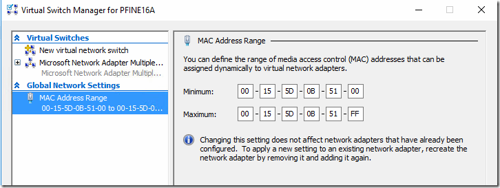
What about SCVMM?

This question usually comes up in relation to RDS, do you need System Center Virtual Machine Manager (SCVMM), can you use SCVMM, how does it integrate? The Citrix XenDesktop solution requires SCVMM as a component of that architecture for VM provisioning but not so for RDS. In the case of RDS, VMM not only is not required at all but there really isn’t a very direct integration path between the products. SCVMM here should be seen as an external management tool to compliment the base set of tools used to manage your Hyper-V Failover Clusters, storage and VMs. So what can you do with VMM in an RDS deployment?
SCVMM can be used as a basic deployment enabler of the environment or a provisioning/ mgmt tool for unmanaged collections, but does not integrate directly with the RDS farm or the RDCB. This means that SCVMM cannot be used to provision any VM intended to exist within a managed pool owned by the RDCB. You can use SCVMM to create VMs for an unmanaged collection or deploy your RDSH VMs while also benefitted from using a much larger pool to manage assignable MAC addresses without worry of conflict or shortage.
To fully appreciate what is possible here it is important to understand the concept of unmanaged and managed collections in RDS. Managed collections are pools that the RDCB creates and maintains using a template VM, including the ability to recreate VMs as needed. Unmanaged collections are pools to which the RDCB brokers connections, but there is no template VM therefore you have to create and manage the pool manually. Everything I’ve shown so far in this series has been “managed” which is the most common deployment style due to ease of ongoing maintenance. If you want to use SCVMM to manage your desktop pool VMs and take advantage of features like Intelligent Placement and a massive MAC address pool, then you will need to use an unmanaged collection. This model is best suited for a 1:1 persistent desktop deployment and as you can see below, can still make use of UPDs.
For example, in this deployment I have SCVMM 2016 running SQL Server 2014 on a dedicated Server 2016 VM. I wish to deploy and manage a large RDS pool of persistent desktops using SCVMM. The first step is to create an unmanaged collection. This is specified during the creation of the collection by unchecking the “Automatically create and manage virtual desktops” option. Select any additionally desired options and deploy.

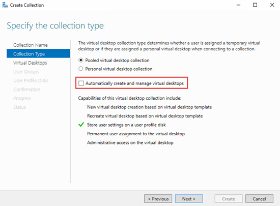
Once the collection is created, clone however many VMs required using SCVMM via PowerShell and spread them across the cluster using SCVMM’s Intelligent Placement feature. There is no way in the SCVMM GUI to clone multiple VMs so this operation is scripted, see Resources at the bottom. This method eliminates the concerns about too few or overlapping MAC addresses and balances the VMs across the cluster automatically based upon available capacity. Once the VMs are created, they then need to be manually added to the new unmanaged collection. This can be done using PowerShell or Server Manager. Once this has been done users will be able to see the collection in RD Web Access and the RDCB will be able to broker user connections to the pool. Thousands of VMs could be deployed this way and brokered using RDCB.

Add-RDVirtualDesktopToCollection -CollectionName Name -VirtualDesktopName Clone1 -ConnectionBroker RDCB.domain.com

Alternatively, VMs can be added to the unmanaged pool using Server Manager.

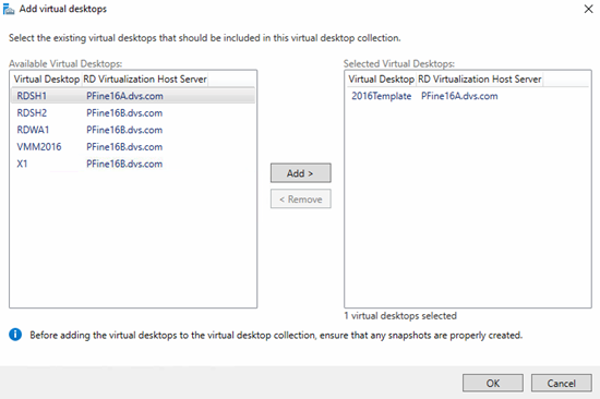
But wait, can’t I manually add existing VMs to a managed collection too? Nope! You can add additional VMs to a managed collection but they must be based on the template already assigned to the collection thus ensuring consistency.
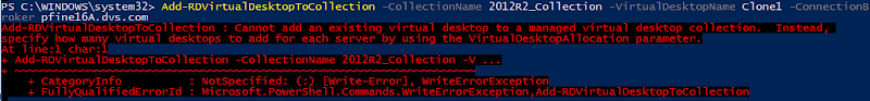
Service Templates
The other use case for SCVMM in the RDS context is for deployment and scaling of the surrounding infrastructure using Service Templates. Within SCVMM, one can create a Service Template to deploy entire or individual pieces of an RDS deployment. The Service Template element within SCVMM provides a visual method to build a master script that is used to provision management server VMs using a specific hardware configuration, with specific applications installed, in a specified order of execution. The possibilities here are nearly limitless as you can have at your disposal the full capability of any application, PowerShell or script. Lock down your Service Templates and you could build, rebuild or expand any deployment with the push of a button.
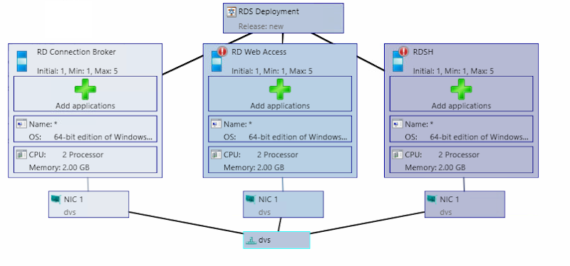
Scaling for Compute

I’ll talk about HA next which inherently brings scalability to the management stack but first, consider compute as part of the architecture. Compute in this context refers to the physical Hyper-V hosts that provide resources for desktop or RDSH VMs, exclusively. The limitations of the compute layer will almost always be based on CPU. It is the one finitely exhaustible resource not easily expanded unless you upgrade the parts. Adjusting resources to provide additional IO, memory or network throughput is a straight-forward process linearly scalable via the capabilities of the server platform. To get the best bang for the buck, most customers seek to deploy the highest reasonable number of users per compute host possible. Hyper-V provides a great deal of CPU efficiency at the expense of slightly higher IO. Depending on the workload and VM profile, one could expect to see 5-10+ VMs per core in an RDS deployment. Compute hosts used for RDSH VMs will require few total VMs per physical host but have the potential to host a much larger number of total users. NUMA architecture alignment is important to ensure maximum performance in these scenarios. A higher number of cores per CPU is generally more important than the clock speed. Considering that it is easy to achieve 256 VMs on a single compute host (default MAC address limit provided by Hyper-V), the appropriate host hardware mix should be selected to ensure the maximum performance and end user experience. Compute hosts can be added to a deployment in block fashion to satisfy a total desired number of users. Keep in mind the nuances of managing a native RDS stack at scale and whether or not it may make sense to invest in 3rd party solutions to bolster your deployment.

Solution High Availability

High-availability can be configured for this solution in a number of different areas. The general principles of N+1 apply at all service levels including physical components. The following guidance will provide a fully redundant RDS infrastructure:

  • Add Top of Rack switching infrastructure for physical port redundancy
  • Add Hyper-V compute and mgmt hosts for failover
    • Hyper-V hosts configured in a failover cluster to protect physical compute resources also using Cluster Shared Volumes to protect storage (ideally cluster mgmt and compute separately)
  • Add load balancers to manage SSL offload and HTTPS connections from clients for RD Gateways and RD Web Access servers
  • Add additional RD Gateway and RD Web Access servers to provide resiliency and redundancy
  • Add additional RDCB servers configured to connect to a clustered SQL Server instance
  • Add a 2nd license server VM configured with temporary licenses, deploy both via GPO but list the primary instance first. Should the primary fail, the secondary will serve the environment using temporary entitlements until the primary is restored.
  • Cluster your file server or add a clustered NAS head back-ended by redundant shared storage for UPDs and user data

Here is another look at the larger architecture but within the context of providing HA:
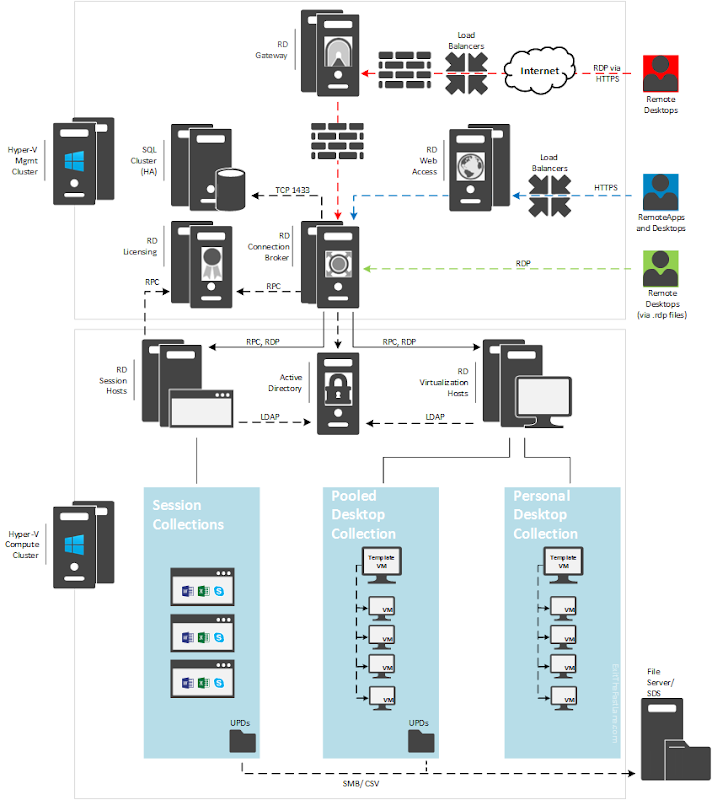
RDCB HA

The RD Broker itself is the most single important role that needs special consideration and configuration to make it HA. Configuring HA for the RDCB creates a cluster with a DNS name assigned for load balancing that keeps track of the location and assignments of user sessions and desktops. First, create a new database on your SQL server with the RDCB server configured to have dbcreator permissions.

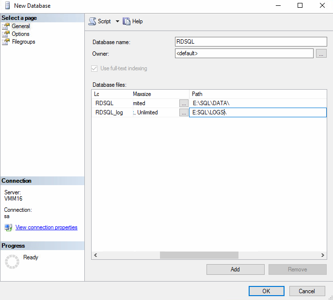
With SQL setup, install the SQL Native Client on all RDCB servers and launch the Configure High Availability wizard from the Deployment Overview.

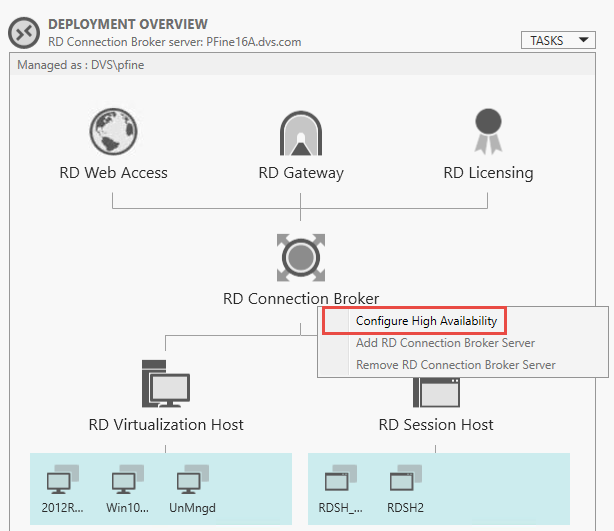
Choose shared SQL mode, name the clustered RDCB instance and provide the SQL connection string in the following format.

DRIVER=SQL Server Native Client 11.0;SERVER=VMM16.dvs.com; Trusted_Connection=Yes;APP=Remote Desktop Services Connection Broker;DATABASE=RDSQL;
         

Once successfully completed, the RDCB will show as HA mode in the Deployment Overview and additional brokers can be added using the same dialog.

RDSH HA

An RDSH collection can be scaled or made HA by adding additional RDSH VMs. Once your new RDSH VMs are created and have the appropriate applications installed, they must be added to the “All Servers” management pool within Server Manager.

Once all hosts or VMs are added to the server management pool, you can add the new VMs to your existing RDS deployment.

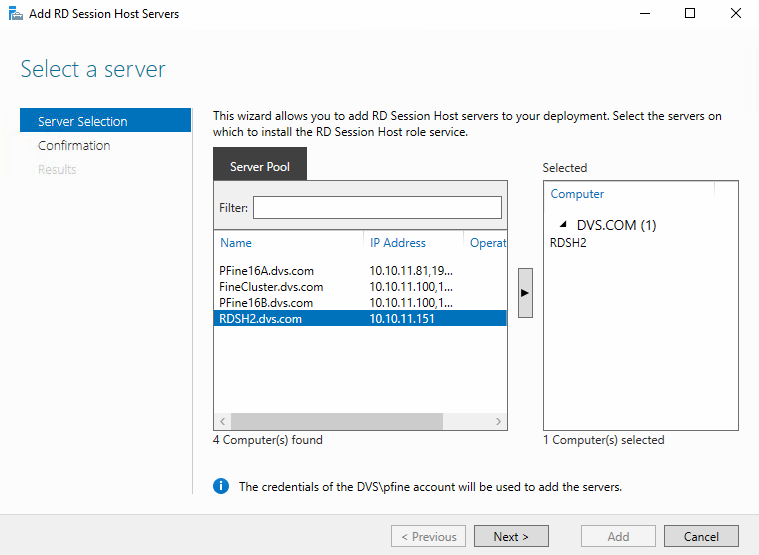
After additional RDSH servers are added to the overall RDS deployment, they can then be added to a specific session collection from the Host Servers dialog of the collection management page.

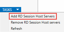
Once successfully added to the collection, all added server instances will be visible and available to accept connections.

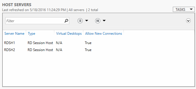
Load balancing between multiple RDSH instances can be configured from within the collection properties dialog to ensure equal distribution or bias, if desired. Making a server “heavier” via relative weight will cause the Connection Broker to push more connections to it accordingly.
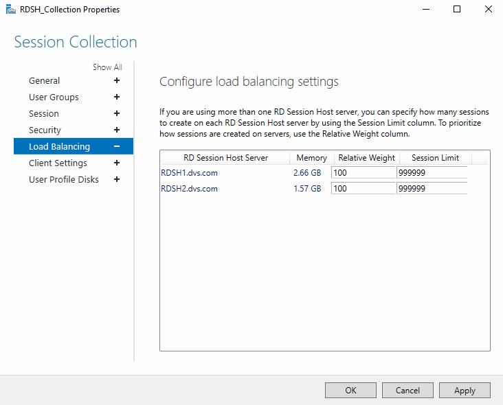
RDWA HA

Additional RD Web Access servers can be added at any time from the Deployment Overview or Deployment Servers dialogs. Select the new server instance you wish to add, confirm and deploy. As always, make sure this server instance is added to the “All Servers” management pool. Behind the scenes IIS is configured on each selected instance to host the website and feed for RDweb.

Once deployed, you should see the new RDWA instance(s) in the RDS Deployment Properties accessible from the RDS Overview page.

Any Collection made to be visible in RD Web Access will be accessible from any RDWA instance. RDWA instances can be accessed directly via URL, load balanced with DNS or put behind a hardware or software load balancer (F5/ Netscaler).

RD Licensing

RD Licensing is one of the trickier roles to make HA as there is no easily exploitable native method to accomplish this. This is generally true regardless of broker solution selected in this space. There are a couple viable methods that require manual intervention that can be used to protect the RD License role. The first method requires two VMs each configured with the RD Licensing role, hosted on separate physical hosts. The first instance has the purchased licenses installed and validated by the Microsoft Clearing House. The second VM is configured with temporary licenses. Both instances are configured via GPO for users but the server with the validated licenses is on the top of the list. Should the primary fail, users can still connect to the environment using temporary licenses until the primary is back online.
The other method also involves two VMs. The primary VM is configured with purchased licenses installed and validated by the Microsoft Clearing House. The VM is cloned, shut down and moved to a separate physical host. Should the primary instance fail for whatever reason, the cold standby can then be powered on to resume the role of the primary. The caveat to this method is that if anything changes from a licensing perspective, the copy to cold stand-by clone process needs to be repeated.

RD Gateway

To optimize and secure connections to the RDS farm from untrusted locations (the interwebs), RDGW can be used and made HA. RDGW terminates SSL for remotely connecting clients, one tunnel for incoming data one for outgoing. UDP can also be utilized for optimized transport of data over WANs using the HTTP transport.  RDGW is installed like any other RDS role and includes IIS as a requisite part of the install. RD Gateway Manager is used to manage the configuration and policies of the gateway including SSL certs and transport settings that provide the ability to change HTTP/UDP listeners. RDGW can also use RD Connection Authorization Policies (RD-CAP) which can be stored locally on the RDGW installed or managed centrally on an NPS server. RDGW can be load balanced as a regular HTTP web service including the offloading of SSL termination. DNS Round Robin is not supported and cannot be used in this scenario.

Failover Clustering and RDS

Lastly, a quick point on the role of Failover Clustering in RDS environments. Failover Clustering is recommended to provide HA for the Hyper-V environment and component level protection of the RDS deployment. Should a node fail or require maintenance in a Failover Cluster, it’s VMs will be restarted or evacuated to another node with available capacity. RDS is cluster aware in that it remains aware of the location of VMs within a Failover Cluster, including if they move around, but it does not integrate directly nor make direct use of the Failover Cluster. In this context the resources for the VMs themselves can be protected giving the management VMs a place to migrate or restart should a failure occur. Any storage added directly to the cluster should be converted to a Cluster Shared Volume enabling multiple simultaneous writers to each volume. RDS itself doesn’t care what the underlying storage is nor whether the environment is clustered or not. Remember that any provisioning activities you perform will address RDVH hosts directly with the RDCB providing the ability to select the number of VMs deployed on each host.

Part 1: The Basics
Part 2: RDVH
Part 3: RDSH
Part 4: Scaling and HA (you are here)

Resources

Creating Service Templates for RDS in SCVMM
Deploying multiple VMs from a template in SCVMM (PoSH)
Hyper-V Dynamic MAC addressing for RDS

Native RDS in Server2016 – Part 3 – RDSH

Part 1: The Basics

Part 2: RDVH

Part 3: RDSH (you are here)

Part 4: Scaling and HA

image[27]

In the first two parts of this series, we explored the basic constructs and architecture of RDS in Server 2016, how to create a farm and how to deploy virtual desktops. In this part we’ll look at integrating RDSH into this environment to provide published applications and shared sessions which compliment a virtual desktop deployment. Many actually start with RDSH or published apps as step 1 then move into virtual desktops to provide greater control or performance.

Looking at the overview page of your RDS deployment, you’ll notice the session host options are greyed out, this is because the deployment (farm) does not currently have these features installed.

image

To add RDSH hosts to an existing RDS deployment, you have to first modify the RDS deployment to enable session-based services. Once your RDSH VMs are created and running within Hyper-V, run the Add Roles and Features Wizard and choose session based deployment. You’re going to have deja vu here but remember, this is all to modify the existing deployment and this is the last time you should need to run this wizard. The wizard will check for the existence of a broker and web access roles which should already exist. Once you get to the RD Session Host part of the dialog, here is where you add your session hosts to the deployment and install the RDSH role on each. Select your target VMs, confirm and deploy. The VMs receiving the RDSH role will be restarted as part of this process.

image     image     image

Via PowerShell (change to your server names):

New-RDSessionDeployment -ConnectionBroker CBname.domain.com -WebAccessServer WAname.domain.com -SessionHost RDSHname.domain.com

Make sure the new servers are added to the Servers pool within Server Manager. At this point you will be able to create a new session collection from the overview page in Server Manager which will no long be greyed out. Give the collection a name, specify the server(s) you want to host the collection and add the user groups you wish to entitle.

image     image     image


Via PowerShell (change to your server names):

New-RDSessionCollection -CollectionName RDSH -SessionHost RDSH.domain.com -ConnectionBroker CBname.domain.com

If you want to use UPDs to persist user settings between sessions, configure the location and size of the UPDs, confirm you selections and deploy.

image

Keep in mind that UPD’s are collection-specific, they cannot be used in more than one collection.     

image

Via PowerShell (change to your server names):

Set-RDSessionCollectionConfiguration -CollectionName RDSH -ConnectionBroker CBname.domain.com -DiksPath C:\ClusterStorage\Volume1\RDSH_UPD -EnableUserProfileDisk -MaxUserProfileDiskSizeGB 1


RD Licensing

By default, RDS will offer a 120-day grace period for licensing, after which you will need to use an RD License server instance with a proper license to suit your licensing mode. The license server activity is a light weight role and can be safely combined with the RD Connection Broker role. From the Deployment Overview page on the main RDS screen, select Add RD Licensing Server. Choose your broker VM and confirm.

image

Edit the deployment properties of your RDS Deployment and choose the RD Licensing section. Select your desired licensing mode and RD License server.

image

To manage your RDS Cals, launch the RD Licensing Manager from the Server Manager Tools menu. Connect to your license server, right-click and select Activate. Complete the information forms and start the Install Licenses Wizard. The wizard will contact the Microsoft ClearingHouse real-time to authorize your server. Microsoft takes licensing of RDSH servers very seriously as there is a tremendous opportunity for software license abuse. Enter the particulars of your license agreement to activate your deployment.

image     image

Another useful tool is the RD Licensing Diagnoser which can help identify problems as well as help achieve compliance. This tool can be launched from the Tools/ Remote Desktop Services menu within Server Manager.

 image


Via PowerShell (change to your server names):

Add-RDServer -Server RDLicName.domain.com -Role RDS-Licensing -ConnectionBroker CBname.domain.com

Set-RDLicenseConfiguration -ConnectionBroker CBname.domain.com -LicenseServer RDLicName.domain.com -Mode PerUser


Managing the Collection

Once the collection is created it will become available for management in Server Manager. Entitlements, RD Web visibility, client settings and UPDs can be manipulated via the collection properties. Idle sessions can be force logged off while active sessions can be shadowed, disconnected, messaged or logged off. RemoteApp Programs provides application virtualization for programs running within the RDSH servers of the pool to RD Web Access. Session collections can offer full session desktops or published applications, but not both. Virtual GPU is not supported for session collections, you’ll need to look to Citrix XenApp for that.

image

Once the collection is created you can either publish specific applications or full shared sessions themselves. Individual applications will launch seamlessly and can even be tied to specific file extensions. If you wish to publish a full shared session desktop, this is very easy to do. Simply edit the properties of the collection via the Tasks dropdown on the collection page and ensure that the box is checked to “Show the session collection in RD Web Access.” This will provide an icon in RD Web that users can click to launch a full desktop experience on the RDSH server.

image

To publish specific applications, select “Publish RemoteApp Programs” from the tasks dropdown in the middle of the page. RDS will poll the RDSH servers currently part of your collection for available apps to publish. As the note at the bottom of the initial dialog says, make sure than any program you wish to publish is installed on all RDSH servers within the collection. Confirm your selections and publish.

image     image     image

Via PowerShell (use $variables and script for multiple apps or repeat command for each):

New-RDRemoteApp -CollectionName RDSH -DisplayName "OpenOffice Calc" -FilePath "%SYSTEMDRIVE%\Program Files (x86)\OpenOffice...scalc.exe" -ShowInWebAccess 1

Connecting to Resources

At this point, anything you have published and entitled will be available in RD Web Access. By default this URL as created within IIS will be https:///RDWeb and should be secured using a proper certificate.You can see below that I now have a mix of RDSH published apps, a RemoteApp Program from a desktop collection, a session collection, as well as a desktop collection. What users will see will vary based on their entitlements.  To enable direct connection to a collection using the Remote Desktop Connection (RDC), a collection within RD Web can be right clicked which will trigger a download of the .rdp file. This file can be published to users and used to connect directly without having to log into RD Web first.

image

Editing the .rdp file in a text editor will reveal the embedded characteristics of the connection which include the client settings, connection broker, gateway and most importantly the collection ID which in this case is “RDSH2”. 

image

RemoteApp Programs can also be delivered directly to a users’ Start menu by connecting the client session to the feed of the RD Web Access Server. This can be configured individually or delivered via GPO. A proper security certificate is required.

image

When a user initiates a connection to a resource with an unknown publisher for the first time they will be greeted with the following dialog. The resources allowed by the remote host can be restricted via deployment properties or GPOs. The RemoteApp will launch within a seamless session window and to the user will appear to be running locally.

image     image

At this point the connection broker does as the name implies and connects users to resources within the deployment while maintaining where VMs are running and which VMs users are logged in to. In the next section we’ll take a look at scaling and HA.

Part 1: The Basics

Part 2: RDVH

Part 3: RDSH (you are here)

Part 4: Scaling and HA

Resources:

RDS Cmdlets for Server 2016

Native RDS in Server2016 – Part 2 – RDVH

Part 1: The Basics
Part 2: RDVH (you are here)
Part 3: RDSH
Part 4: Scaling and HA

image[27]

In part 1 of this series we took a look at the over all architecture of RDS in Server 2016 along with the required components  contrasting the function performed by each. If you’re not new to RDS, things really haven’t changed a great deal from Server 2012R2 from a basic architecture perspective. In this chapter we’ll take a look at the RDVH role, what it does, how to get going and how to manage it.

Test Environment

Here is a quick rundown of my environment for this effort:

  • Servers – 2 x Dell PowerEdge R610’s, dual X5670 (2.93GHz) CPUs, 96GB RAM, 6 x SAS HDDs in RAID5 each
  • Storage – EqualLogic PS6100E
  • Network – 1Gb LAN, 1Gb iSCSI physically separated
  • Software – Windows Server 2016 TP5 build 14300.rs1
  • Features – Hyper-V, RDS, Failover Clustering

Installation

The first step is to create an RDS deployment within your environment. Consider this construct to exist as a farm that you will be able to install server roles and resources within. Once the initial RDS deployment is created, you can create and expand collections of resources. An RDS deployment is tied to RD Connection Broker(s) which ultimately constitute the farm and how it is managed. The farm itself does not exist as an explicitly addressable entity. My hosts are configured in a Failover Cluster which is somewhat inconsequential for this part of the series. I’ll explain the role clustering plays in part 4 but the primary benefits are being able to use Cluster Shared Volumes, Live Migration and provide service HA.
On one of your management hosts that already has Hyper-V enabled, fire up the Add Roles and Features Wizard, select Remote Desktop Services installation and choose your deployment model. “Standard” would be what is chosen most often here unless doing a POC then “Quick Start” may be more appropriate. MultiPoint is something entirely different which carries a different set of requirements. You don’t have to use this wizard but it is an easy way to get going. I’ll explain another way in a moment.

image     image 

Next choose whether you’ll be deploying desktop VMs or sessions. Desktops require the RDVH role on the parent, sessions require RDSH and can be enabled within Server VMs. For this portion we’ll be focusing on RDVH.

SNAGHTML463b08fe      image

Next select the hosts or VMs to install the RD Connection Broker and Web Access roles. For POCs everything on one host is ok, for production it is recommended to install these RDS roles onto dedicated Server VMs. You’ll notice that I pointed the wizard at my Failover Cluster which ultimately resolved to a single host (PFine16A).

image     image    

The third piece in this wizard is identifying the host(s) to assume the RDVH role. Remember that RDVH goes on the physical compute host with Hyper-V. Confirm your selections and deploy.

image     image

The installation will complete and affected hosts or VMs will be restarted. In order to manage your deployment, all Hyper-V hosts and server VM roles that exist within your deployment must be added to the Servers tab within Server Manager. This can be done at the very beginning as well, just make sure it gets done or you will have problems.
image

At this point your RDS deployment should be available for further configuration with the option to create additional roles or a desktop collection. Unless you are building a new RDS deployment, when adding additional server roles, it is much easier to select the role-based installation method from the Add Roles and Features Wizard and choose the piece-parts that you need. This is especially true if adding singular roles to dedicated server VMs. There is no need to rerun the “Remote Desktop Services Installation” wizard, in fact it may confuse things.
image

Desktop VM Templates and Collections

Before we create a new collection, we need to have a template VM prepared. This can be a desktop or server OS but the latter requires some additional configuration. By default, the connection broker looks for a desktop OS SKU when allowing a template VM to be provisioned. If you try to use a Server OS as your template you will receive the following error:
image[20]

To get around this, you must add the following registry key to any host that sources or owns the master template. Reboot and you will be allowed to use a Server OS as a collection template.

HKLM\System\CurrentControlSet\Services\VMHostAgent\Parameters\SkipVmSkuValidation   REG_DWORD     1

Your template should be a normal VM (Gen 1 or 2), fully patched, desired software installed and manually sysprepped. That’s right, RDS does not integrate the ability to auto-clone a template VM to new unique VMs, you need to do this manually as part of your collection prep.
image

Make sure whatever template you intend to provision in your desktop collection is already added to your RDVH host or cluster and powered off.
image[2]

Launch the Create Collection wizard within Server Manager, give the collection a name and select pooled or personal desktops.

image     image

Select the template VM to use to create the collection, if using a Server OS make sure you completed the steps above to make the template VM visible and selectable in the RD Collection wizard. Keep in mind that a template VM can only be used in a single collection, no sharing allowed. Provide an answer file if you have one or use the wizard to generate the settings for time zone and AD OU.
image     image     image

Specify the users to be entitled to this collection and the number of desktops you wish to deploy along with the desired naming convention. For allocation, you can now decide how many VMs of the total pool to provision to each available physical host. Take note of this, VMM is not here to manage Intelligent Placement for you, you can accept the defaults or decide how many VMs to provision to a host.

image     image

     
Select where to store the VMs: this can be a local or shared drive letter, SMB share or CSV. The ability to use CSVs is one of the benefits of using Failover Clustering for RDS deployments. Next, if you intend to use UPDs for storing user settings, specify the path and size you want to allocate to each user. Again, CSVs work fine here. Confirm and deploy.
image     image     image

Behind the scenes, RDS is making a replica of your template VM’s VHDX stored in the volume you specified, which it will then clone to the collection as new VMs.
image

The pooled VMs themselves are thin provisioned, snapped (checkpointed) and only consume a fraction of the storage consumed by the original template. When reverting back to a pristine state at log off, the checkpoint created during provisioning is applied and any changes to the desktop OS are discarded.
image

UPDs are ultimately VHDX files that get created for each user that connects to the collection. By default all user profile data is stored within a UPD. This can become unwieldy if your users make heavy use of the Desktop, Documents, Music, etc folders. You can optionally restrict which pieces should be stored within the UPD and use folder redirection for the others if desired.
image

When UPD is enabled for a collection, there is a template UPD created within the volume specified then each user gets a dedicated UPD with the SID of the user as the file name. Selected settings are saved within and follow the user to any session or desktop they log into within the collection. This file will grow up to the maximum allotted.
image

Managing the Collection

Depending on the speed of your hardware, your pooled VMs will deploy one by one and register with the broker. Once the collection is deployed it will become available for management in Server Manager. Entitlements, RD Web visibility, client settings and UPDs can be manipulated via the collection properties. Desktop VMs can be manipulated with a basic set of controls for power management, deletion and recomposition. RemoteApp Programs provides a way to publish applications running within the desktop pool to RD Web Access without requiring RDSH or RD Lics which may be useful in some scenarios. Virtual GPU can also be enabled within a desktop collection if the host is equipped with a supported graphics cards. Server 2016 adds huge improvements to the Virtual GPU stack.
image

Notice here that RDS is aware of which VMs are deployed to which hosts within my cluster. Should a VM move between physical hosts, RDS will see that too. When removing VMs from a collection, always do this from the Collections dialog within Server Manager as it’s a cleaner process. This will turn off the VM and remove it from Hyper-V. If you delete a VM from Hyper-V manager, the RDS broker will report that VM as unknown in Server Manager. You will then need to delete it again from within Server Manager.

image     image         

If you have an AD object that already exists with the same machine name, that VM will fail to provision. Make sure that if you redeploy any collection using the same names that AD is also cleaned up before you do so.
image

As is always the case when working with VMs in Hyper-V, manual file system cleanup is required. Deleting a VM from Hyper-V or RDS in Server Manager will not remove the files associated with the VM. You could always add them back if you made a mistake but otherwise you will need to manually delete or script an operation to do this for you.
image[17]

RemoteApp Programs can be used to publish applications for users of a desktop collection. This does not require RDSH but it will only allow a single user to connect to a published resource, just like a desktop VM. If you use RemoteApp Programs within a desktop collection, you will be unable to publish the desktop collection itself. For example, I have Google Chrome published from one desktop within my collection, this prevents the entire collection from being presented in RD Web Access only allowing the published app. To make this collection visible in RD Web Access again, I have to unpublish all RemoteApp Programs from the collection then select to show the collection in RD Web Access. The same is true of session collections. You can publish apps or you can publish sessions but not both simultaneously within a single collection.
image

Connecting to Resources

Logging into RD Web Access is the easiest way to access published resources. By default this URL as created within IIS will be https:///RDWeb and can be secured using a proper certificate. Depending on user entitlements, users will see published apps, sessions or desktops available for launching. To enable direct connection to a collection using the Remote Desktop Connection (RDC), a collection within RD Web can be right clicked which will trigger a download of the .rdp file. This file can be published to users and used to connect directly without having to log into RD Web first.
image

Editing the .rdp file in a text editor will reveal the embedded characteristics of the connection which include the client settings, connection broker, gateway and most importantly the collection ID which in this case is “RDC”. 
image

At this point the connection broker does as the name implies and connects users to resources within the deployment while maintaining where VMs are running and which VMs users are logged in to. In the next section we’ll take a look at integrating RDSH into this environment.

Part 1: The Basics
Part 2: RDVH (you are here)
Part 3: RDSH
Part 4: Scaling and HA

Native RDS in Server2016 – Part 1 – The Basics

Part 1: The Basics (you are here)
Part 2: RDVH
Part 3: RDSH
Part 4: Scaling and HA
image
As is the case with a number of Microsoft workload technologies, particularly in the End User Compute (EUC) space, Microsoft provides you with the basic tools to fulfill a particular requirement or use case. If you want to get more granular with management or fancier with features, your next step would be to invest into their partner ecosystem to expand upon the base offering. Such is and always has been the case with Remote Desktop Services (RDS). Remote Desktop Virtualization Host (RDVH) and Remote Desktop Session Host provide a very functional, but basic solution for virtual desktops or shared sessions. If you want greater granularity with an increased feature set while wanting to stay on Hyper-V, you can upgrade into the Citrix XenDesktop or XenApp product space. If you want to use vSphere as your hypervisor you could run RDSH VMs natively or add greater management granularity and features by buying into the VMware Horizon product space. At the end of the day, no matter which way you go, if you intend to deploy shared sessions or shared virtualized applications, as most environments do initially, Microsoft RDSH is the technology underneath it all. This series will cover the what, why and how of the native Microsoft RDS stack for Server 2016.

Use Cases

The first thing to decide is whether you need shared sessions/ published apps (most common) or dedicated pooled or personal virtual desktops assigned 1:1 to each user. RDSH is the most widely deployed technology in this space and where most environments initially invest to virtualize published applications or deploy a shared hosted workspace. If the shared session/ app solution falls short in any way or if users need greater dedicated performance, the next step is to isolate users via pooled or personal virtual desktops. Pooled desktops can be refreshed for each new user (non-persistent) while personal desktops are dedicated to a user (persistent). Pooled desktops or shared sessions can make use of User Profile Disks (UPD) which store user settings and folders in a central location. A collection can make use of both folder redirection as well as UPDs.
Virtual desktops are completely complimentary to published applications which can reduce the complexity of the template used for a collection while lowering the resource consumption of VMs running within. This is done by offloading the running applications to RDSH hosts keeping the desktop VMs leaner thereby yielding greater density per compute host. Multipoint is now an installable role in Server 2016 RDS which is useful for single-server multi-user scenarios not requiring RDP across the network. For Server 2016 all uses cases can be built on-premise, in the cloud, or a hybrid of the two. This blog series will focus on the on-premise variety which is also most common.

What’s new in RDS 2016

Personal Session Desktops – A new type of session collection that allows users to be assigned to a dedicated RDSH VM (Azure deployments)
Gen2 VMs – Full support for Gen2 VM templates for pooled/ personal VM collections and personal session desktop collections
Pen Remoting – Surface Pro stylus devices available for use in RDS
Edge browser support
RemoteFX Virtual GPU – OpenGL, OpenCL, DX12, CUDA, 4K resolution, Server OS VMs, 1:1 Direct Device Assignment
Windows Multipoint Services – Now a part of RDS as an installable role for super low cost single server solutions, RDSH required
RDP10 – h.264/ AVC 444 codec, open remoting
Scale – RD Connection Broker capable of supporting 10K concurrent connection requests

Solution Components

At a very basic level, if you want shared sessions you need the RDSH role enabled on physical hosts or Server VMs. If you want virtual desktops you need Hyper-V and the RDVH role enabled on the physical host/ parent partition. Best practices suggest that only Hyper-V and RDVH roles be enabled on physical hosts, all other roles should exist within VMs to enable better scale, HA and portability. It is important to note that neither SQL Server nor System Center Virtual Machine Manager (SCVMM) are required for a basic RDS deployment.
The RDS management infrastructure for Server 2016 has two deployment scenario roles and four Services roles which can be deployed within a single VM for POCs or very small environments.

Hosts

  • Compute hosts – Hyper-V hosts used for the sole purpose of running RDSH VMs or pooled and personal desktop VMs.
  • Management hosts – Hyper-V hosts used for the sole purpose of running RDS infrastructure components such as Connection Brokers and Web Access servers.

Deployment Roles

  • RDVH – Virtualization Host role provides the ability to deploy pooled or personal desktops within Hyper-V, organized via collections. Enabled within parent partition of Hyper-V enabled host.
  • RDSH – Session Host role provides the ability to deploy servers or VMs hosting shared sessions or published applications, organized via collections. Can be enabled within physical or dedicated RDSH Server VMs.

Services Roles

  • RD Connection Broker – The broker is the heart of the operation and connects users to their desktops, sessions or apps while load balancing amongst RDSH and RDVH hosts. This role is mandatory.
  • RD Gateway – The gateway role is used to securely connect internet-based users to their session, desktop or app resources on the corporate network. This role is optional.
  • RD Web Access – Enables users to access RemoteApp and Desktop Collections via the Start menu or web browser. This role is mandatory.
  • RD Licensing – Manages the licenses required for users to connect to RDSH sessions, virtual desktops or apps. This role is mandatory after 120 days.

Collection Deployment Options

  • Sessions/ apps – Users connect via RDP to a RDSH host or VM to run a full desktop experience or a published app. All users connected to a single RDSH host share the physical resources of that host. In 2016 users can be configured to connect to a dedicated RDSH host (useful for Azure and desktop licensing rules).
  • Pooled desktops – Non-persistent desktop VMs created within a collection that have power state and automatic rollback capabilities to create fresh VMs for each user login. User settings can be stored on a UPD.
  • Personal desktops – Persistent desktop VMs created within a collection that have power state managed and are permanently assigned to a user of the desktop. This collection type does not require nor support the use of UPDs.
  • User Profile Disks – UPDs can be added to any session or pooled desktop collection to persist user profile data between session or desktop connection activities. One UPD per user.

View of the various RDS infrastructure roles as portrayed within Server Manager:
image

Architecture

Here are all those pieces showcased in a basic distributed architecture, separating resources based on compute and management roles as I like to do in our Dell solutions. You’ll notice that there are a couple of ways to connect to the environment depending on where the user is physically as well as which resource they need to connect to. SQL Server is listed for completeness but is only required if you intend to add HA to your RDS deployment. Pooled (non-persistent) and Personal (persistent) desktops are functionally similar in that they are both based on a template VM to deploy the collection but only sessions and pooled collections can make use of a UPD. The storage hosting the UPDs is illustrated below as external to the management hosts but it could also be a file server VM that exists within. This RDS architecture can be deployed using traditional shared storage, software defined, or local disk.
image

Part 1: The Basics (you are here)
Part 2: RDVH
Part 3: RDSH
Part 4: Scaling and HA

Resources

Technet

Enterprise VDI

My name is Peter and I am the Principal Engineering Architect for Desktop Virtualization at Dell. 🙂

VDI is a fire hot topic right now and there are many opinions out there on how to approach it. If you’re reading this I probably don’t need to sell you on the value of the concept but more and more companies are deploying VDI instead of investing in traditional PC refreshes. All trending data points to this shift only going up over the next several years as the technology gets better and better. VDI is a very interesting market segment as it encompasses the full array of cutting edge enterprise technologies: network, servers, storage, virtualization, database, web services, highly distributed software architectures, high-availability, and load balancing. Add high capacity and performance requirements to the list and you have a very interesting segment indeed! VDI is also constantly evolving with a very rich ecosystem of players offering new and interesting technologies to keep up with. This post will give you a brief look at the enterprise VDI offering from Dell.
As a customer, and just 1 year ago I still was one, it’s very easy to get caught up in the marketing hype making it difficult to realize the true value of product or platform. With regard to VDI, we are taking a different approach at Dell. Instead of trying to lure you with inconceivable and questionable per server user densities, we have decided to take a very honest and realistic approach in our solutions. I’ll explain this in more detail later.
Dell currently offers 2 products in the VDI space: Simplified, which is the SMB-focused VDI-in-a-box appliance I discussed here (link), and Enterprise which can also start very small but has much longer legs to scale to suit a very large environment. I will be discussing the Enterprise platform in this post which is where I spend the majority of my time. In the resources section at the bottom of this posting you will find links to 2 reference architectures that I co-authored. They serve as the basis for this article.

DVS Enterprise

Dell DVS Enterprise is a multi-tiered turnkey solution comprised of rack or blade servers, iSCSI or FC storage built on industry leading hypervisors, software and VDI brokers. We have designed DVS Enterprise to encompass tons of flexibility to meet any customer need and can suit 50-50,000 users. As apposed to the more rigid “block” type products, our solutions are tailored to the customer to provide exactly what is needed with flexibility for leveraging existing investments in network, storage, and software.
The solution stacks consist of 4 primary tiers: network, compute, management, and storage. Network and storage can be provided by the customer, given the existing infrastructure meets our design and performance requirements. The Compute tier is where the VDI sessions execute, whether running on local or shared storage. The management tier is where VDI broker VMs and supporting infrastructure run. These VMs run off of shared storage in all solutions so management tier hosts can always be clustered to provide HA. All tiers, while inextricably linked, can scale independently.
image

The DVS Enterprise portfolio consists of 2 primary solution models: “Local Tier 1” and “Shared Tier 1”. DVS Engineering spends considerable effort validating and characterizing core solution components to ensure your VDI implementation will perform as it is supposed to. Racks, blades, 10Gb networking, Fiber Channel storage…whatever mix of ingredients you need, we have it. Something for everyone.

Local Tier 1

“Tier 1” in the DVS context defines from which disk source the VDI sessions execute and is therefore faster and higher performing disk. Local Tier1 applies only to rack servers (due to the amount of disk required) while Shared Tier 1 can be rack or blade. Tier 2 storage is present in both solution architectures and, while having a reduced performance requirement, is utilized for user profile/data and management VM execution. The graphic below depicts the management tier VMs on shared storage while the compute tier VDI sessions are on local server disk:

image

This local Tier 1 Enterprise offering is uniquely Dell as most industry players focus solely on solutions revolving around shared storage. The value here is flexibility and that you can buy into high performance VDI no matter what your budget is. Shared Tier 1 storage has its advantages but is costly and requires a high performance infrastructure to support it. The Local Tier 1 solution is cost optimized and only requires 1Gb networking.

Network

We are very cognizant that network can be a touchy subject with a lot of customers pledging fierce loyalty to the well-known market leader. Hey I was one of those customers just a year ago. We get it. That said, a networking purchase from Dell is entirely optional as long you have suitable infrastructure in place. From a cost perspective, PowerConnect provides strong performance at a very attractive price point and is the default option in our solutions. Our premium Force10 networking product line is positioned well to compete directly with the market leader from top of rack (ToR) to large chassis-based switching. Force10 is an optional upgrade in all solutions. For the Local Tier 1 solution, a simple 48-port 1Gb switch is all that is required, the PC6248 is shown below:

image

Servers

The PowerEdge R720 is a solid rack server platform that suits this solution model well with up to 2 x 2.9Ghz 8-core CPUs, 768GB RAM, and 16 x 2.5” 15K SAS drives. There is more than enough horsepower in this platform to suit any VDI need. Again, flexibility is an important tenet of Dell DVS so other server platforms can be used if desired to meet specific needs.

Storage

A shared Tier 2 storage purchase from Dell is entirely optional in the Local Tier 1 solution but is a required component of the architecture. The Equallogic 4100X is a solid entry level 1Gb iSCSI storage array that can be configured to provide up to 22TB of raw storage running on 10k SAS disks. You can of course go bigger to the 6000 series in Equallogic or integrate a Compellent array with your choice of storage protocol. It all depends on your need to scale.

image

Shared Tier 1

In the Shared Tier 1 solution model, an additional shared storage array is added to handle the execution of the VDI sessions in larger scale deployments. Performance is a key concern in the shared Tier 1 array and contributes directly to how the solution scales. All Compute and Mgmt hosts in this model are diskless and can be either rack or blade. In smaller scale solutions, the functions of Tier 1 and Tier 2 can be combined as long as there is sufficient capacity and performance on the array to meet the needs of the environment. 

image

Network

The network configuration changes a bit in the shared Tier 1 model depending if you are using rack or blades and what block storage protocol you employ. Block storage traffic should be separated from LAN so iSCSI will leverage a discrete 10Gb infrastructure while fiber channel will leverage an 8Gb fabric. The PowerConnect 8024F is a 10Gb SFP+ based switch used for iSCSI traffic destined to either Equallogic or Compellent storage that can be stacked to scale. The fiber channel industry leader Brocade is used for FC fabric switching.

In the blade platform, each chassis has 3 available fabrics that can be configured with Ethernet, FC, or Infiniband switching. In DVS solutions, the chassis is configured with the 48-port M6348 switch interconnect for LAN traffic and either Brocade switches for FC or a pair of 10Gb 8024-K switches for iSCSI. Ethernet-based chassis switches are stacked for easy management.

Servers

Just like the Local Tier 1 solution, the R720 can be used if rack servers are desired or the half-height dual-socket M620 if blades are desired. The M620 is on par to the R720 in all regards except for disk capacity and top end CPU. The R720 can be configured with a higher 2.9Ghz 8-core CPU to leverage greater user density in the compute tier. The M1000E blade chassis can support 16 half-height blades.

Storage

Either Equallogic or Compellent arrays can be utilized in the storage tier. The performance demands of Tier 1 storage in VDI are very high so design considerations dealing with boot storms and steady-state performance are critical. Each Equallogic array is a self-contained iSCSI storage unit with an active/passive controller pair that can be grouped with other arrays to be managed. The 6110XS, depicted below, is a hybrid array containing a mix of high performance SSD and SAS disks. Equallogic’s active tiering technology dynamically moves hot and cold data between tiers to ensure the best performance at all times. Even though each controller now only has a single 10Gb port, vertical port sharing ensures that a controller port failure does not necessitate a controller failover.

Compellent can also be used in this space and follows a more traditional linear scale. SSDs are used for “hot” storage blocks especially boot storms, and 15K SAS disks are used to store the cooler blocks on dense storage. To add capacity and throughput additional shelves are looped into the array architecture. Compellent has its own auto-tiering functionality that can be scheduled off hours to rebalance the array from day to day. It also employs a mechanism that puts the hot data on the outer ring of the disk platters where they can be read easily and quickly. High performance and redundancy is achieved through an active/active controller architecture. The 32-bit Series 40 controller architecture is soon to be replaced by the 64-bit SC8000 controllers, alleviating the previous x86-based cache limits.

Another nice feature about Compellent is its inherent flexibility. The controllers are flexible like servers allowing you to install the number and type of IO cards you require: FC, iSCSI, FCoE, and SAS for the backend… Need more front-end bandwidth or add another backend SAS loop? Just add the appropriate card to the controller.
In the lower user count solutions, Tier 1 and Tier 2 storage functions can be combined. In the larger scale deployments these tiers should be separated and scale independently.

VDI Brokers

Dell DVS currently supports both VMware View 5 and Citrix XenDesktop 5 running on top of the vSphere 5 hypervisor. All server components run Windows Server 2008 R2 and database services provided by SQL Server 2008 R2. I have worked diligently to create a simple, flexible, unified architecture that expands effortlessly to meet the needs of any environment.

image

Choice of VDI broker generally lands on customer preference, while each solution has its advantages and disadvantages. View has a very simple backend architecture consisting of 4 essential server roles: SQL, vCenter, View Connection Server (VCS) and  Composer. Composer is the secret sauce that provides the non-persistent linked clone technology and is installed on the vCenter server. One downside to this is that because of Composer’s reliance on vCenter, the total number of VMs per vCenter instance is reduced to 2000, instead of the published 3000 per HA cluster in vSphere 5. This means that you will have multiple vCenter instances depending on how large your environment is. The advantage to View is scaling footprint, as 4 management hosts are all that is required to serve a 10,000 user environment. I wrote about View architecture design previously for version 4 (link).

image

View Storage Accelerator (VSA), officially supported in View 5.1, is the biggest game changing feature in View 5.x thus far. VSA changes the user workload IO profile, thus reducing the number of IOPS consumed by each user. VSA provides the ability to enable a portion of the host server’s RAM to be used for host caching, largely absorbing read IOs. This reduces the demand of boot storms as well as makes the tier 1 storage in use more efficient. Before VSA there was a much larger disparity between XenDesktop and View users in terms of IOPS, now the gap is greatly diminished.
View can be used with 2 connection protocols, the proprietary PCoIP protocol or native RDP. PCoIP is an optimized protocol intended to provide a greater user experience through richer media handling and interaction. Most users will probably be just fine running RDP as PCoIP has a greater overhead that uses more host CPU cycles. PCoIP is intended to compete head on with the Citrix HDX protocol and there are plenty of videos running side by side comparisons if you’re curious. Below is the VMware View logical architecture flow:

XenDesktop (XD), while similar in basic function, is very different from View. Let’s face it, Citrix has been doing this for a very long time. Client virtualization is what these guys are known for and through clever innovation and acquisitions over the years they have managed to bolster their portfolio as the most formidable client virtualization player in this space. A key difference between View and XD is the backend architecture. XD is much more complex and requires many more server roles than View which affects the size and scalability of the management tier. This is very complex software so there are a lot of moving parts: SQL, vCenter, license server, web interfaces, desktop delivery controllers, provisioning servers… there are more pieces to account for that all have their own unique scaling elements. XD is not as inextricably tied to vCenter as View is so a single instance should be able to support the published maximum number of sessions per HA cluster.

image

One of the neat things about XD is that you have a choice in desktop delivery mechanisms. Machine Creation Services (MCS) is the default mechanism provided in the DDC. At its core this provides a dead simple method for provisioning desktops and functions very similarly to View in this regard. Citrix recommends using MCS only for 5000 or fewer VDI sessions. For greater than 5000 sessions, Citrix recommends using their secret weapon: Provisioning Server (PVS). PVS provides the ability to stream desktops to compute hosts using gold master vDisks, customizing the placement of VM write-caches, all the while reducing the IO profile of the VDI session. PVS leverages TFTP to boot the VMs from the master vDisk. PVS isn’t just for virtual desktops either, it can also be used for other infrastructure servers in the architecture such as XenApp servers and provides dynamic elasticity should the environment need to grow to meet performance demands. There is no PVS equivalent on the VMware side of things.
With Citrix’s recent acquisition and integration of RingCube in XD, there are now new catalog options available for MCS and PVS in XD 5.6: pooled with personal vDisk or streamed with personal vDisk. The personal vDisk (PVD) is disk space that can be dedicated on a per user basis for personalization information, application data ,etc. PVD is intended to provide a degree of end user experience persistence in an otherwise non-persistent environment. Additional benefits of XD include seamless integration with XenApp for application delivery as well as the long standing benefits of the ICA protocol: session reliability, encrypted WAN acceleration, NetScaler integration, etc.  Below is the Citrix XenDesktop logical architecture flow:

High Availability

HA is provided via several different mechanisms across the solution architecture tiers. In the network tier HA is accomplished through stacking switches whether top of rack (ToR) or chassis-based. Stacking functionally unifies an otherwise segmented group of switches so they can be managed as a single logical unit. Discrete stacks should be configured for each service type, for example a stack for LAN traffic and a stack for iSCSI traffic. Each switch type has its stacking limits so care has been taken to ensure the proper switch type and port count to meet the needs of a given configuration.

Load balancing is provided via native DNS in smaller stacks, especially for file and SQL, and moves into a virtual appliance based model over 1000 users. NetScaler VPX or F5 LTM-VE can be used to load balance larger environments. NetScalers are sized based on required throughput as each appliance can manage millions of concurrent TCP sessions.
Protecting the compute tier differs a bit between the local and shared tier 1 solutions, as well as between View and XenDesktop. In the local tier 1 model there is no share storage in the compute tier, so vSphere HA can’t help us here. With XD, PVS can provide HA functionality by controlling the placement of VDI VMs from a failed host to a hot standby.

The solution for View is not quite so elegant in the local tier 1 model as there is no mechanism to automatically move VMs from a failed host. What we can do though is mimic HA functionality by manually creating a resource reservation on each compute host. This creates a manual RAID type of model where there is reserve capacity to host a failed server’s VDI sessions.

In the shared tier 1 model, the compute tier has shared storage so we can take full advantage of vSphere HA. This also applies to the management tier in all solution models. There are a few ways to go here when configuring admission control. Thankfully there are now more options than only calculating slot sizes and overhead. The simplest way to go is specifying a hot standby for dedicated failover. The downside is that you will have gear sitting idle. If that doesn’t sit well with you then you could specify a percentage of cluster resources to reserve. This will thin the load running on each host in the cluster but at least won’t waste resources entirely.

If the use of DRS is desired, care needs to be taken in large scale scenarios as this technology will functionally limit each HA cluster to 1280 VMs.

Protection for the storage tier is relatively straight forward as each storage array has its own built-in protections for controllers and RAID groups. In smaller solution stacks (under 1000 users) a file server VM is sufficient to host user data, profiles, etc. We recommend that for deployments larger than 1000 users that NAS be leveraged to provide this service. Our clustered NAS solutions for both Equallogic and Compellent are high performing and scalable to meet the needs of very large deployments. That said, NAS is available as an HA option at any time, for any solution size.

Validation

The Dell DVS difference is that our solutions are validated and characterized around real-world requirements and scenarios. Everyone that competes in this space plays the marketing game but we actually put our solutions through their paces. Everything we sell in our core solution stacks has been configured, tested, scrutinized, optimized, and measured for performance at all tiers in the solution. Additional consulting and blue printing services are available to help customers properly size VDI for their environments by analyzing user workloads to build a custom solution to meet those needs. Professional services is also available to stand up and support the entire solution.

The DVS Enterprise solution is constantly evolving with new features and options coming this summer. Keep an eye out here for more info on the latest DVS offerings as well as discussions on the interesting facets of VDI.

References:

Dell DVS: VMware View Reference Architecture 

Dell DVS: Citrix XenDesktop Reference Architecture

Hands on with the Cisco UCS C200 M2

The hype machine in Cisco channel land has been working overtime since Cisco started shipping its new USC line of servers and blade center. If you’ve heard what is being said, Cisco is basically claiming to have reinvented the server and is now offering unparalleled performance over their competitors. Their one large claim to fame on the onset was their VMware VMark scores, but as of this writing HP has bested them in every category by small margins. The other key selling point is Cisco’s Extended Memory Technology which allows an increased amount of physical RAM in UCS servers aimed at providing greater virtual machine density.

Cisco, in my view,  has never been a company overly concerned about sexiness in their hardware or software, although they certainly tried harder than usual with their king Nexus 7000 switch. The UCS C200 servers I have acquired will be used to power a new virtualized Unified Communications infrastructure (Call Manager) which is another major advancement in Cisco’s product offerings. So while my use case will not push these servers to their theoretical performance limits, I will still get down and dirty with this new hardware platform. 

Under the hood

My first impression of the C200 is that it looks remarkably similar to an older lower-end Dell PowerEdge or SuperMicro white box server. Aesthetically pretty vanilla, at this level anyway. That said, the layout is simple and gets the job done in true minimalist fashion. All internal components are OEM’d from the usual suspects: Intel, Samsung, Seagate, LSI… Getting the cover off of this thing is truly a pain requiring a lot of hard release button mashing and downward forceful pushing. Both of my C200’s were like this so definitely not a fluke.


The C200 ships with 2 Gigabit NICs for host traffic and 1 NIC for out of band management (CIMC). VGA and USB ports are in the rear with a proprietary KVM dongle port on the front of the server. 2 expansion slots and dual power supplies are also available. Although effective, I dislike this style of power cord retainer which is also used by NetApp.
 
 
The rail kit is where Cisco really dropped the ball as I guess they assumed that all their customers would be using extended depth racks. The rails are tool-less snap-ins with adjustable slides, the problem is that the rail itself does not adjust and cannot be made any shorter.
 
 
For standard depth racks the tail of these rails stick out past the posts.
 
 
I had to rack this server in the middle of my rack or the tail on the right side would block a row of PDU ports. (wtf!)
 

Cisco Integrated Management Controller (CIMC)

CIMC is the remote out-of-band management solution (IPMI) provided with Cisco servers. With the very mature HP ILO and Dell DRAC remote management platforms around for years, Cisco’s freshman attempt in this space is very impressive indeed. All of the basic data and functionality you would expect to find is here plus a lot more. Access to the CIMC GUI requires Adobe Flash via a web browser which is visually pretty but disappointing to see in an enterprise platform. They certainly aren’t the only major vendor to start trending this direction (read: VMware View 4.5).

Performance is a bit slow for tabs on some pages where the hardware has to be polled and display data refreshed. But when that data eventually trickles in, the level of detail is dense.

The Network Adapters tab was misbehaving for me on both of my servers. After a few seconds all these amazing options disappear and an error:timed out pop-up appears. This will be incredible once they (assumedly) fix their code. Notice the tabs in the middle for vNICs and vHBAs intended to provide tight virtualization integration.


Really great detail…


That was all just from the Inventory page! More great detail is revealed in the Sensors section with multiple readings and values for each core component of the server.

There are a few other notable features that Cisco has included that are particularly cool. One of which is the ability to configure certain BIOS parameters from within the CIMC.
 
 
Some variables that can only be configured during boot time in other platforms can be changed via CIMC, although some if not most of these changes will require a reboot to take effect.


Other user, session, logs, and firmware management options include all the usual settings and variables. One other neat option in the Utilities sub menu is the ability to reboot CIMC, reset it to factory default as well as import configurations! That’s huge and will make managing multiple servers much more coherent. All told and bugs aside, the potential of CIMC is very impressive.

Call Manager –  the virtual edition


A major shift for Cisco, now available in CUCM Version 8.x, is the ability to deploy the enterprise voice architecture inside of VMware ESXi. Call manager, and it’s sister voice mail service Unity Connection, are just Linux servers (RHEL 4) after all so this makes perfect sense. You can now deploy Call Manager and Unity clusters inside of a virtual space while leveraging the HA provided by VMware as well.

This of course doesn’t come without its caveats. Currently Cisco does not support VMs living outside of Cisco servers and that includes storage. So you will have to buy a Cisco server to deploy this solution as well as keep the VMs on Cisco disk, not your own corporate SAN. You can use your own VMware licensing and vCenter at least which is a good thing. Once Cisco has established a comfortable foothold in the enterprise server market, look for these policies to ease a bit. Right now they need to sell servers!

To ensure that partners and customers deploy CUCM in a consistent fashion, Cisco has released open virtual machine templates (OVA) for their deployments. OVAs keep things nice and clean, even if you won’t agree with their choice of virtual hardware (LSI Logic parallel vs LSI SAS). CUCM is still managed the same way, via web browser, and the interface is exactly the same in v8 as it was in v7.x.
 

Not purely Cisco-related, but a minor observation that others have noticed as well is that ESXi incorrectly reports the status of Hyper-Threading support on non-HT Intel-based servers. My C200 is equipped with Xeon E5506 CPUs which do not support HT. Not a big deal, just an observation. If HT was available in this CPU I would definitely enable it as ESX(i) 4.1 can now schedule much more efficiently with the new Intel CPU architectures.

Wrap

All in all there’s a lot to like about the new Cisco offerings. A commitment to virtualization and hardware optimized to run virtual workloads are smart investments to make right now. There are some physical design choices that I don’t particularly care for but this model server is at the bottom of the platform stack, so maybe more consideration was paid to the platforms at the top? CIMC was carefully constructed and, although buggy right now, shows some real innovation over competing platforms in this space. More companies that would not have otherwise been able to buy into a full-blown Call Manager cluster configuration can now do so with reduced hardware investments.

References:
Cisco OVA templates

Split-Scope DHCP in Server 2008 R2

Splitting DHCP scopes is a best practice that has been around for a very long time. The purpose is to spread a given IP scope across multiple DHCP servers in multiple locations for redundancy and load balancing. Let’s say that your company has two locations, A and B; Location A has two DHCP servers, location B has one. The IP schemes are different at each location but you want to ensure that DHCP services are available for all IP scopes at both should any of the DHCP servers ever have a problem. The best way to achieve this is to spread the scopes across all three servers. This is done by defining the scope on each server then configuring exclusions for the IP range that each server should not serve, to avoid overlap. While this was all possible in previous versions of Windows Server it had to be configured manually.

Server 2008 R2 makes this easier by adding a split-scope wizard in the DHCP MMC. First configure a DHCP scope as you normally would with the first and last IP address that you want to be dynamically assigned. Leave out the range of the IP space you intend to use for static assignments as we are only concerned with dynamic assignments. Once the scope has been defined and created it can be split by invoking the split-scope wizard in the advanced sub menu of the scope.

image

Once you have Selected the authorized server that you would like to add to the scope, the wizard will allow you to define the percentage of the address space that you want to give to the new server. Move the slider left and right to adjust the pool given to the new server you are configuring. If you plan to split the scope across 3 or more servers, do some quick math to determine how many addresses each should serve if you want to split the scope evenly. In the example below I am keeping 33% of the address space on the original server and giving 67% to the new server because I plan to split the scope again. The bottom portion of the window displays the exclusions that will be created on both the original host and new server.

SNAGHTMLb349de

Next you can configure a server offer delay so you can help shape which servers you want to be able to respond in which order. I intend to make my third server primary for this scope so will configure delays for both the host and added DHCP servers.

SNAGHTMLbbe996

Before executing the split you are presented with a summary screen to ensure that your configuration is correct. Once you execute, the wizard will create an exclusion on the host server as well as create the new scope with exclusion on the added server. A time saver for sure!

SNAGHTMLc0ecf1

The wizard runs through each required step and displays the result of each.

SNAGHTMLc3ae9a

On the newly added server the scope is not automatically activated so if you made a mistake you can easily start over by deleting the new scope on the added server and the exclusion on the host server. Repeat this process on the second server to split the scope again ensuring an even split across all 3 servers. Once your configuration is solid all you need to do is activate the scope on each server you added it to.

image

Here is how the scope and exclusions look on each server after the split.

Original host:

image

2nd added server:

image

3rd added server:

image

As you can see best practice is automatically applied by defining the entire DHCP range on each server, then limiting the assignable range on each through an exclusion. Future adjustments can be made easily by changing the exclusion.

As a final step, make sure you have IP helpers configured in your switch on the proper VLAN interfaces so it knows where to send your client’s DHCPDISCOVER messages.

SNAGHTMLd13382

Hey where did my drive space go??!?

This one is easy to overlook and can have you scratching your head weeks to months later. Recently disk space has been mysteriously disappearing on a few select servers of mine. The free/used ratio was way out of whack with >75% of the disk being reported as used by Windows on certain drives. Auditing the drive reveals no culprit, with all visible files not consuming anything near what is being reported, including hidden files. System Volume Information reports 0 bytes and access is denied to this folder. If you use Windows Server Backup (WSB), in Server 2008 R2, and in particular VSS backups this can happen to you too (or VSS at all for that matter).

WSB uses VSS for backups and you have two choices in your backup sets: VSS full or copy backups.

 image

In either case the backup job will create a Shadow Copy task on the volume pertaining to your backup. By default the shadow copy task is set to use no limit which will, eventually, completely consume your drive. The tricky part is that the space consumed by VSS is not visible in Windows Explorer and if you don’t set a hard limit on the shadow copy it can grow out of control.

image

Make sure to limit these and you should be ok. Changing no limit to use limit will immediately delete and free space on your server!

image

VSS settings are accessed by opening the properties of any drive in your server and selecting the Shadow Copies tab.

How to control DNS resolution for an external domain

I recently had a situation come up where I needed to change the traffic flow on my LAN for Outlook Anywhere clients that were going out to the internet to connect to our email provider (outlookanywhere.domain.com). Our provider is also accessible internally via a disparate and complicated network so the internet method was preferred due to less complexity. The Outlook Anywhere public facing servers were having problems, denying my client connections, so I needed to force the connections internally.

Caveats:

  • I still want my clients to be able to access Outlook Anywhere outside the office so I can’t disable it or change the address it connects to
  • HOSTS files are unmanageable
  • I do not own the namespace of the servers that Outlook Anywhere connects to
  • I will have to statically route to each destination in the provider’s namespace (from my core network) as our networks are connected but not well routed

To pull this off there are a few available options:

  • Leverage conditional forwarders to the affected namespace
  • Create a new primary DNS zone for this namespace, add the host record I need to redirect
  • Create a new primary DNS zone for each FQDN that I want to redirect

The first option is the simplest, I could just route all of the requests to this domain directly to its internal DNS servers. The problem with this is that I’ll have to also statically route to every possible server/host in that network that users might access. There are too many.

The second option would also work but then I’d need to create A records for any other hosts in that namespace or clients would be unable to resolve them.  The routing problem exists here too so this is a bad option for me.

The third option is the money ticket. Using this method I can simply create a new forward lookup zone for outlookanywhere.domain.com and in that zone create a nameless A record with the internal IP of that server. Easy. I still have to statically route to this server but all other public facing resolutions will continue to work without issue. This solution will work for any external namespace if you need to redirect your internal clients somewhere else.

Review: Citrix XenApp Fundamentals 3

The XenApp (XA) brand was a name change that continues the Citrix Presentation Server (CPS) product line. CPS 4.5 for Server 2003 ended and XenApp 5 for Server 2008 x86 began. Citrix has recently released XA 6 which is 64-bit and designed to run on Server 2008 R2. Citrix Essentials, the scaled down SMB product, was renamed to Citrix Fundamentals (XAF). XAF is akin to XA 5 functionally for all intensive purposes. XenApp 5 and 6 come in Advanced, Enterprise, and Platinum flavors, each unlocking different features.

XAF is targeted for small to medium enterprises that need only a maximum of 75 named users. That is the main drawback, concurrent licensing is not available on this platform. The idea is simplicity and XAF achieves that goal handily while providing a full XA experience. When installing XAF you are presented with 2 installation types: application or DMZ (secure gateway). The intended design is for the Secure Gateway to sit in a firewalled DMZ (single-hop) and point to the application server sitting on the LAN inside.

image

Installing the application server piece is incredibly simple with the installer taking care of everything including all prerequisites. Make sure to enable Remote Desktop Services prior to install with all licensing requirements taken care of.

image

Once the “Set Up Server” wizard launches, you have a choice to configure a stand-alone server or a server group. Advanced mode can be enabled now or later which unlocks user profile management, load balancing, and server failover. The advanced features rely heavily upon Active Directory and currently only Server 2008 R1 functional-level domains are supported. The OU structure will be created in 2008 R2 domains but the advanced mode initialization will ultimately fail. Citrix is aware of the issue and says that we should see some kind of fix in 2-3 weeks.

image

Once setup completes, launch the Quick Start tool and add your license file. I am using evaluation licenses provided by Citrix for this trial.

image

The Quick Start tool walks you through the steps to get your sever up and running, including publishing apps, linking up with the Secure Gateway (if you choose), publishing printers, and delegating administrative access. Application installations work just like any other terminal server install, start up “install app in TS-mode” and install. Then the application can be published, assigned to user groups/ servers, associated with file types, and appearance controlled. You can open the familiar Citrix Access Management console at any time to complete any of these tasks.

image

Performance optimizations can be set at the farm or server levels and include Session Reliability, CPU/Memory Optimization, etc.

image

The Web Interface is fully customizable providing options for authentication methods , secure access, and internal/external web site appearance.

image image image

The External Access server portion (Secure Gateway) is even simpler. Again all requisite components are taken care of by setup.

image

Once setup completes the Quick Start tools launches displaying the External Access options.

image

Configuring the gateway consists of specifying the FQDN it will respond to on the internet and the address of the internal Citrix application server. You can generate a temporary SSL certificate but you’ll have to install the cert and add the issuer as a trusted publisher before your applications will be usable. I opted to use a free comodo cert instead. The last step is opening TCP/1080 through your firewall from your DMZ server to your internal application server. That’s it.

The Secure Gateway has its own Web Interface which can be customized in appearance as well. Additionally you can choose which plugins to publish and whether or not the native plugin should be preferred. All of the other Web Interface options are available here as well.

image

The default login form is clean and simple. Domain names can be required to login using a UPN or domain\username formats. Assuming the domain name that resolves to your Secure Gateway does not have the same name as your internal domain, this can add some easy additional security.

image

Once authenticated, if you don’t have the Citrix client you will be directed to a screen where you can download and install it before you continue. Once installed you will be presented with your published applications. Access to your enterprise is now a click away.

image

Performance is very good and there are no issues running the entire solution in a virtual environment. Application Isolation as it was known in CPS is gone in XenApp, replaced by Application Streaming. This feature is only available in the Enterprise and Platinum versions. After my environment was set up, anytime I closed an app I also saw the Server 2008 logoff screen. While not a huge deal this disturbs the seamless Citrix user experience. To get around this I added a logoff script to the user portion of my terminal server baseline GPO. Create a .bat file and put the following in it, no more logoff screens:

tsdiscon %sessionname%

Licensing is roughly $100 per concurrent user for XAF, plus the TS CAL, plus any applicable application licensing. Definitely not a cheap solution, especially since Server 2008 includes Remote Apps by default. Like most out-of-the-box Microsoft solutions what they give you is adequate but if you want all the bells and whistles you have to go third-party. I plan to completely replace my legacy Cisco VPN solution with Citrix as well as provide an environment to run applications with Windows7 compatibility problems. Home user PCs and whatever nightmares they harbor will stay in their homes. Citrix provides a secure, reliable, and rich user experience that will ultimately reduce support calls and make application maintenance easier.

As with any terminal server environment, the challenges will come with publishing apps and ensuring that users have access to all the proper resources. I ran into another issue publishing Office 2003 SP3 to satisfy a companion legacy reporting application. Not having any application isolation options to publish Office 2003 along side 2007, I decided to publish Office 2003 with the 2007 compatibility pack. Office itself worked fine but to get the compatibility pack converters to work I had to use some trickery. wordconv.exe as well as the excel and ppt converters had to be added to the DEP exception list. I also had to enable compatibility mode for all users on the core executables themselves (winword.exe, etc). With these changes in place I was able to open and edit 2007 file formats without issue. All told I’m very pleased with XAF and if they fix the advanced mode compatibility issues with 2008 R2 domains I’ll be ecstatic. If anything pushes me towards XA Enterprise though, it will be application streaming.