VMware vSphere HA Mode for vGPU

The following post was written and scenario tested by my colleagues and friends Keith Keogh and Andrew Breedy of the Limerick, Ireland CCC engineering team. I helped with editing and art. Enjoy.

VMWare has added High Availability (HA) for virtual machines (VM’s) with an NVIDIA GRID vGPU shared pass-through device in vSphere 6.5. This feature allows any vGPU VM to automatically restart on another available ESXi host with an identical NVIDIA GRID vGPU profile if the VM’s hosting server has failed. 
To better understand how this feature would work in practice we decided to create some failure scenarios. We tested how HA for vGPU virtual machines performed in the following situations:
1)  Network outage: Network cables get disconnected from the virtual machine host.
2)  Graceful shutdown: A host has a controlled shut down via the ESXi console.
3)  Power outage: A host has an uncontrolled shutdown, i.e. the server loses AC power.
4)  Maintenance mode: A host is put into maintenance mode.

The architecture of the scenario used for testing was laid out as follows:  

ao

Viewed another way, we have 3 hosts, 2 with GPUs, configured in an HA VSAN cluster with a pool of Instant Clones configured in Horizon.

clus1
image

1)  For this scenario, we used three Dell vSan Ready Node R730 servers configured per our C7 spec, with the ESXi 6.5 hypervisor installed, clustered and managed through a VMWare vCenter 6.5 appliance.
2)  VMWare VSAN 6.5 was configured and enabled to provide shared storage.
3)  Two of the three servers in the cluster had an NVIDIA M60 GPU card and the appropriate drivers installed in these hosts. The third compute host did not have a GPU card.
4)  16 vGPU virtual machines were placed on one host. The vGPU VM’s were a pool of linked clones created using VMWare Horizon 7.1. The virtual machine Windows 10 master image had the appropriate NVIDIA drivers installed and an NVIDIA GRID vGPU shared PCI pass through device added.
5)  All 4GB of allocated memory was reserved on the VM’s and the M60-1Q profile assigned which has a maximum of 8 vGPU’s per physical GPU. Two vCPU’s were assigned to each VM.
6)  High Availability was enabled on the vSphere cluster.

Note that we intentionally didn’t install an M60 GPU card in the third server of our cluster. This allowed us to test the mechanism that allows the vGPU VM’s to only restart on a host with the correct GPU hardware installed and not attempt to restart the VM’s on a host without a GPU. In all cases this worked flawlessly, the VM’s always restarted on the correct backup host with the M60 GPU installed.

s1

Scenario One

To test the first scenario of a network outage we simply unplugged the network cables from the vGPU VM’s host server. The host showed as not responding in the vSphere client and the VM’s showed as disconnected within a minute of unplugging the cables.  After approximately another 30 seconds all the VM’s came back online and restarted normally on the other host in the cluster that contained the M60 GPU card.

Scenario Two
s2

A controlled shutdown down of the host through ESXi worked in a similar manner. The host showed as not responding in the vSphere client and the VM’s showed as disconnected as the ESXi host began shutting down the VSAN services as part of ESXi’s shutdown procedure. Once the host had shut down, the VM’s restarted quite quickly on the backup host. In total, the time from starting the shutdown of the host until the VM’s restarted on the backup host was approximately a minute and a half.

s3

Scenario Three

To simulate a power outage, we simply pulled the power cord of the vGPU VM’s host. After approximately one minute the host showed as not responding and the VM’s showed as disconnected in the vSphere client. Roughly 10 seconds later the vGPU VM’s had all restarted on the back up host.

s4

Scenario Four

Placing the host in maintenance mode worked as expected in that any powered on VMs must first be powered off on that host before completion can occur. Once powered off, the VM’s were then moved to the backup host but not powered on (the ‘Move powered-off and suspended virtual machines to other hosts in the cluster’ option was left ticked when entering maintenance mode). The vGPU-enabled VM’s were moved to the correct host each time we tested this: the host with the M60 GPU card.

In conclusion, the HA failover of vGPU virtual machines worked flawlessly in all cases we tested. In the context of speed of recovery, we made the following observations with regard to the scenarios tested. The unplanned power outage test recovered the quickest at 1 minute 10 seconds followed by the controlled shutdown, with the network outage taking slightly longer again to recover.

Failure ScenarioApproximate Recovery Time
Network Outage1 min, 30 sec
Controlled Shutdown1 min, 30 sec
Power Outage1 min, 10 sec

In a real world scenario the HA failover for vGPU VM’s would of course require an unused GPU card in a backup server for it to work. In most vGPU environments you would probably want to fill the GPU to its maximum capacity of vGPU based VM’s to gain maximum value from your hardware. In order to provide a backup for a fully populated vGPU host, it would mean having a fully unused server and GPU card lying idle until circumstances required it. It is also possible to split the vGPU VM’s between two GPU hosts, placing, for example 50% of the VM’s on each host. In the event of a failure the VM’s will failover to the other host. In this scenario though, each GPU would be used to only 50% of its capacity.

An unused back-up GPU host may be ok in larger or mission critical deployments but may not be very cost effective for smaller deployments. For smaller deployments it would be recommended to leave a resource buffer on each GPU server so that if there was a host failure, there is room on the GPU enabled server to facilitate these vGPU Enabled VM’s.

vSphere Design for NUMA Architecture and Alignment

I’m publishing this design topic separately for both Hyper-V and vSphere, assuming that the audience will differ between the two. Some of this content will be repeated between posts but arranged to focus on the hypervisor each prospective reader will likely care most about.
Be sure to also check out: Hyper-V Design for NUMA Architecture and Alignment: Link

Non-Uniform Memory Access (NUMA) has been with us for awhile now and was created to overcome the scalability limits of the Symmetric Multi-Processing (SMP) CPU architecture. In SMP, all memory access was tied to a singular shared physical bus. There are obvious limitations in this design, especially with higher CPU counts and increased traffic on the bus.

image

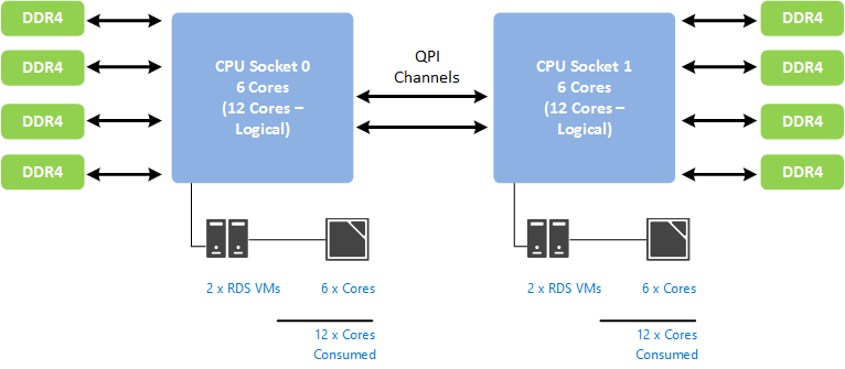
NUMA was created to limit the number of CPUs tied to a single memory bus and as a result defines what is construed as a NUMA node. A high performing NUMA node is defined by the memory directly attached to a physical CPU socket in turn accessed directly by consuming applications and services. The memory controller is on-die and the memory DIMMs connect directly to the CPU socket.  The total number of logical cores available to a NUMA node is double if Hyperthreading is enabled. Per the example below, I have a dual socket system with 6 physical cores per CPU, including hyperthreading there are 12 logical cores per physical NUMA node, netting a total of 24 logical cores in the system.

image

NUMA spanning occurs when memory or CPU cores are accessed remote to the NUMA node an application, service or VM is connected. NUMA spanning means your application or service won’t run out of memory or CPU cores within its NUMA node as it can access the remote DIMMs or cores of an adjacent CPU. The problem with NUMA spanning is that your application or service has to cross the lower performing processor interconnects to store its pages in the remote DIMMs or access remote cores. The maximum vCPU value assignable to a VM is dictated by the total number of logical cores available in all NUMA nodes.

What is NUMA alignment?

In the case of virtualization, VMs created on a physical server receive their vCPU entitlements from the physical CPU cores of their hosts (um, obviously). There are many tricks used by hypervisors to oversubscribe CPU and run as many VMs on a host as possible while ensuring good performance. Better utilization of physical resources = better return on investment and use of the company dollar. To design your virtual environment to be NUMA aligned means ensuring that your VMs receive vCPUs and RAM tied to a single physical CPU (pCPU), thus ensuring the memory and pCPU cores they access are directly connected and not accessed via traversal of a CPU interconnect (QPI). As fast as interconnects are these days, they are still not as fast as the connection between a DIMM and pCPU. Ensuing that your virtual environments are NUMA aligned means ensuring the highest possible performance.

Running many smaller 1 or 2 vCPU VMs with lower amounts of RAM, such as virtual desktops, aren’t as big of a concern and we generally see very good oversubscription at high performance levels with less need to span NUMA. In the testing my team does at Dell for VDI architectures, we see somewhere between 9-12 vCPUs per pCPU core depending on the workload and VM profile. For larger server-based VMs, such as those used for RDSH sessions, this ratio is smaller and more impactful because there are fewer overall VMs consuming a greater amount of resources. In short, NUMA alignment is much more important when you have fewer total VMs with larger vCPU and RAM allocations.

To achieve sustained high performance for a dense server workload, it is important to consider:

    1. The number of  vCPUs assigned to each VM within a NUMA node to avoid contention.
    2. The amount RAM assigned to each VM to ensure that all memory access remains local within a physical NUMA node.

The easiest method to follow is to ensure that your VMs receive vCPUs in an even multiple of the total logical cores available per NUMA node. The following is an example of a balanced configuration based on a dual 6-core, 96GB server used for RDSH. The server hosts 6 high performance VMs that are configured within 2 NUMA node boundaries. Given the number of vCPUs and RAM assigned to each VM, each NUMA node is oversubscribed 2x from a pCPU core perspective (including hyperthreading) and does not exceed the 48GB of RAM available to each pCPU socket. This ensures that NUMA spanning is not required and minimizes potential contention amongst the VMs. Your oversubscription ratio may vary depending on workload or SLAs. For RDSH specifically, the best results are achieved using 1.5x or 2x oversubscription. Here is an example of a NUMA aligned configuration with 4 VMs:

image

vNUMA in vSphere

In vSphere 5.0 and later, the virtual NUMA topology can be exposed to the guest OS as long as it is hardware version 8 or later. vNUMA is enabled by default if a VM is configured with more than 8 total vCPUs (or 4 vCPU cores + 2 cores per NUMA node) and will match the host where it was powered on until the VM is restarted. This minimum number can be adjusted if desired as shown later.
When the NUMA topology is exposed to a guest VM, one of two things happen via the ESXi NUMA scheduler:

    1. If a VM is assigned a vCPU value less than or equal to the number of total logical cores in a physical NUMA node, then this VM will be assigned to a single physical NUMA node and consume memory/ cores local to that node (ideal). This remains true until that VM is configured to access more memory than what is available in the single physical NUMA node, which would result in the VM spanning to the remote NUMA node (less than ideal).
    2. If a VM is assigned more vCPUs than cores that exist in a single physical NUMA node, it will be assigned to at least 2 physical NUMA nodes. This will satisfy the resource requirements of the VM but will come with a performance penalty as the VM spans local and remote NUMA nodes (less than ideal).

Some conditions will cause VMs to not be managed by the ESXi NUMA scheduler, such as enabling CPU Hot Add or manual specification of a VM’s CPU or memory affinity. This effectively disables vNUMA and carries some obvious inherent risks.
The NUMA scheduler assigns each VM to a “home node” at boot time which is a defined physical NUMA node within the server. ESXi tracks NUMA nodes within the System Resource Allocation Table (SRAT). When calculating a VM’s NUMA home node, hyperthreading is ignored. So if your VM is configured with more vCPUs that a single physical CPU has cores, it will be assigned to 2 or more NUMA home nodes. ESXi will ensure VM memory locality by locking a VM to run from the same home node that contains its assigned memory. If system load changes such that a VM’s home node is no longer optimal, ESXi can dynamically migrate a VM to a new home node. Part of this migration could also include a migration of the VM’s memory assignment to prevent spanning NUMA if possible. Important to note that if you set CPU affinity for a VM, this essentially disables the NUMA scheduler for that VM.
There are 2 ways you can verify how many NUMA nodes are present according to what ESXi sees, via esxtop or esxcli. From the console of one of your hosts run esxtop. Once running, press “m” to enable memory stats. Later, to see the NUMA stats as they apply to VMs, from esxtop press “f” to change the fields displayed, select NUMA Stats with “g” and hit any key to exit.
image

As you can now see, ESXi is aware of 2 physical NUMA nodes in my test system each with 49GB memory directly attached to each node.
image

The second method is the “easy” way but displays less information overall. Run the following esxcli command which also reveals that this host has 2 NUMA nodes:

esxcli hardware memory get | grep NUMA

image

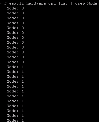
Further, just to completely remove any doubt about the number of logical cores available and to which physical NUMA node they belong, consider the following output from esxcli. 12 logical CPUs assigned to each physical node.

esxcli hardware cpu list | grep Node

image

NUMA Alignment in vSphere

The basic principles of NUMA are the same when dealing with vSphere or Hyper-v however executed slightly differently from a VM perspective. My vSphere cluster shares the same specs of my Windows cluster:

  • 2 x Dell PowerEdge R610’s with dual X5670 6-core CPUs and 96GB RAM running vSphere 5.5 U2 in an HA Cluster. 24 total logical hyperthreaded processors as reported by ESXi.

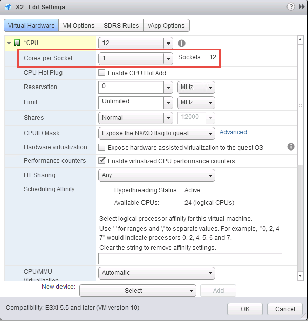
vNUMA can be altered on a VM by VM basis through vCPU assignments or via advanced host settings if global tweaks need to be made. It’s worth noting here that although the vSphere Client will allow you to assign CPU cores as well as “cores per socket” to your VMs, this is generally not required. VMware added this option in previous versions to provide the ability to control the number of sockets seen by the guest OS as a way to get around certain software restrictions and limitations that likely no longer apply. In vSphere a vCPU is a vCPU and will be scheduled according to how it fits into the exposed vNUMA topology. You can specify the cores per socket which will affect the NUMA topology presented to the VM, but also realize that this could have negative impacts as to how well that VM plays within the presented topology. Unless you have a good reason to change this, leave the default value of 1 core per socket when configuring VMs in ESXi. In my test servers a single VM can be configured with up to 24 vCPUs and if it’s a Windows server OS, up to 24 sockets, which constitutes the maximum logical configuration of all available cores on this host. Take for example a Server 2012 R2 VM called “X2” configured with 12 vCPUs using the default of 1 core per socket.

image

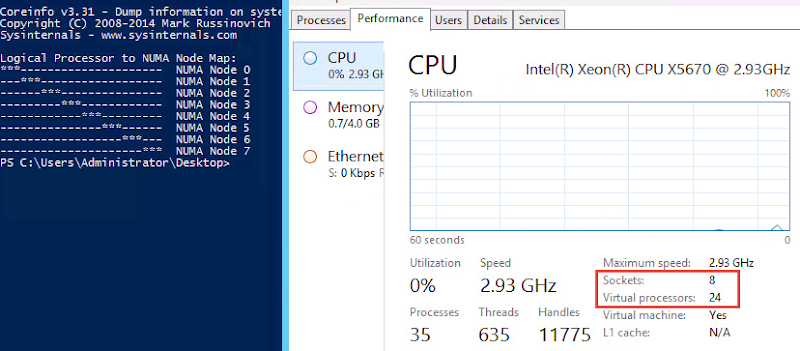
Using the Sysinternals Coreinfo tool we can view the virtual NUMA topology presented to the VM, but keep in mind this is not always indicative of the physical NUMA node assignment. With 12 vCPUs assigned, at 1 core per socket (12 sockets), ESXi exposes the VM to 2 vNUMA nodes. Note that this topology is virtual but at 12 vCPUs fits within a single physical NUMA node:
image
Because the number of vCPUs is >6, ESXi assigns this VM to both NUMA home nodes, shown here in esxtop via the NUMA Home Node (NHN) value. Remember that the NUMA Scheduler ignores the hyperthreaded cores when making this calculation:
image
Even though at 12 vCPUs this VM fits within the logical boundaries of a single physical NUMA node, this VM is assigned to more vCPUs than the 6 physical cores that exist in a single NUMA node, thus enabling ESXi to reserve the right to schedule this VM’s CPU consumption on either NUMA node. If this VM were to be assigned 13 vCPUs, not only would it be assigned to both NUMA home nodes as we see above but it would span NUMA to fulfill it’s operational requirements. Per the diagram below you can see that two similarly configured VMs fit within the constraints of each NUMA node from an assigned memory perspective, but because X2 is configured with more vCPUs than total logical cores that exist on one NUMA node, it must cross the QPIs to fully satisfy its entitlement.
image
Another example of vNUMA in action is the assignment of 24 vCPUs to this VM using an arbitrary 3 cores per socket. vNUMA creates 8 NUMA nodes (sockets) with 3 processors assigned to each.
image
The other example that would cause a VM to span NUMA would be if it were assigned to more memory than what exists within a single physical NUMA node. For this example I’ve reconfigured my X2 VM with 6 vCPUs to ensure CPU locality but assigned and reserved more memory than what exists within the NUMA home node to which it is assigned.
image
For NUMA spanning to actually take place the VM now has to actually consume more memory than what exists in the NUMA home node it was assigned. To do this I used a memory allocation tool and consumed 48GB of active memory. Hopping back over to esxtop we can see exactly the amount of memory being used locally (NLMEM) vs memory spanning to the remote NUMA node (NRMEM).
image

To illustrate what is happening here, X2 is utilizing memory from its assigned NUMA home node but is also having to access the remote NUMA node to store its memory pages. If the cluster didn’t have enough resources available for the configuration of the VM, it would fail to power on.
image
There are a number of additional tweaks available in the Advanced System Settings for a given host or at the individual VM level. Be extremely careful here and only change something if you have education and purpose.

image

To allow a VM with fewer than 8 vCPUs to be managed by vNUMA, a configuration parameter entry must be added to its .vmx file. Open the settings of the VM to be configured, under the VM Options tab, expand Advanced and click Edit Configuration beside Configuration Parameters. Look for the entry “numa.vcpu.min” and edit its value, if it’s not there add this entry and specify the number of vCPUs you need in the value. This would be useful in scenarios where you have fewer VMs with larger memory assignments.

image

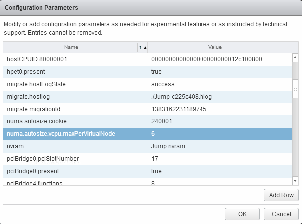
The numa.autosize.vcpu.maxPerVirtualNode value assigned from within a VM’s configuration parameters, can be used to control the vNUMA topology presented to a VM. By default, based on the physical characteristics of my test servers, the value is 6 vCPUs per node as presented to the VM. This can be adjusted up or down if required.
image

Key Takeaways

  • As a matter of general best practice, assign vCPU values to VMs less than or equal to the number of physical cores on a single NUMA node.
  • Designing your virtual infrastructure to work in concert with the physical NUMA boundaries of your servers will net optimal performance and minimize contention.
  • A single VM consuming more vCPUs than a single NUMA node contains, will be scheduled across multiple NUMA nodes causing possible CPU contention.
  • A single or multiple VMs consuming more RAM than a single NUMA node contains will span NUMA and store a percentage of their pages in the the remote NUMA node causing reduced performance.
  • In vSphere vNUMA is enabled by default for VMs with 8+ vCPUs (adjustable) but enabling “hot add CPU” or configuring CPU affinity will essentially disable this feature. Be careful if you do this. 
  • When the NUMA Scheduler calculates which NUMA home node to assign a VM to, hyperthreading is ignored. This calculation is based on the physical cores of the CPUs.

Resources:

http://lse.sourceforge.net/numa/faq/
NUMA in ESXi
http://www.vmware.com/pdf/Perf_Best_Practices_vSphere5.5.pdf
https://blogs.vmware.com/vsphere/2013/10/does-corespersocket-affect-performance.html
http://pubs.vmware.com/vsphere-55/topic/com.vmware.ICbase/PDF/vsphere-esxi-vcenter-server-55-resource-management-guide.pdf
https://pubs.vmware.com/vsphere-60/topic/com.vmware.ICbase/PDF/vsphere-esxi-vcenter-server-60-resource-management-guide.pdf

Dell XC730 – Graphics HCI Style

Our latest addition to the wildly popular Dell XC Web-Scale Converged Appliance series powered by Nutanix, is the XC730 for graphics. The XC730 is a 2U node outfitted with 1 or 2 NVIDIA GRID K1 or K2 cards suited for highly scalable and high-performance graphics within VDI deployments.  The platform supports either Hyper-V with RemoteFX or VMware vSphere 6 with NVIDIA GRID vGPU.  Citrix XenDesktop, VMware Horizon or Dell Wyse vWorkspace can be deployed on the platform and configured to run with the vGPU offering. Being a graphics platform, the XC730 currently supports up to 2 x 120w 10, 12, or 14-core Haswell CPUs with 16 or 32GB 2133MHz DIMMs. The platform requires a minimum of 2 SSDs and 4 HDDs with a range of options within each tier. All XC nodes come equipped with a 64GB SATADOM to boot the hypervisor and 128GB total spread across the first 2 SSDs for the Nutanix Home. Don’t know what mix of components to choose or how to size your environment? No problem, we create optimized platforms and validate them to make your life easier.


image

Optimized High Performance Graphics

Our validated platform for the XC730 is a high-end “B7” variant that provides the absolute pinnacle of graphics performance in an HCI offer. 14-core CPUs, 256GB RAM, dual K2’s, 2 x 400GB SSDs and 4 x 1TB HDDs. This is all about graphics so we need more wattage and the XC730 comes equipped with dual 1100w PSUs. iDRAC8 comes standard in the XC Series as well as your choice of 10Gb SFP+ or BaseT Ethernet adapters. I chose this mix of components to provide a very high-end experience to support the maximum number of users allowed by the K2 vGPU profiles. Watch this space for additional optimized platforms designed to remove the guess of sizing graphics in VDI. Even when GPUs are present, the basic laws of VDI exist which state: thou shalt exhaust CPU first. Dual 14-core parts will ensure that doesn’t happen. Make sure to check out our Appliance Architectures at the bottom of this post for more detailed info.


image


NVIDIA GRID vGPU

The cream of the crop in server virtualized graphics comes courtesy of NVIDIA with the K1 and K2 Kepler-based boards. The K2 has 4x the CUDA cores of the K1 board with a slightly lower core clock and less total memory. The K2 is the board you want for fewer higher end users. The K1 is appropriate for a higher overall number of lower end graphical users. vGPU is where the magic happens as graphics are hardware-accelerated to the virtual environment running within vSphere.  Each desktop VM within the vGPU environment runs a native set of the NVIDIA drivers and addresses a real slice of the server grade GPU. The graphic below from NVIDIA portrays this quite well.


image

(image courtesy of NVIDIA)


The magic of vGPU happens within the profiles that ultimately get assigned. Both K1 and K2 in conjunction with vGPU have a preset number of profiles that ultimately control the amount of graphics memory assigned to each desktop along with the total number of desktops that can be supported by each card. The profile pattern is K2xxx for K2 and K1xxx for K1, the smaller index identifying a great user density. The K280Q and K180Q are basically pass-through profiles where an entire physical GPU is passed through to a desktop VM. You’ll notice how the densities change per card and per GPU depending on how these profiles are assigned. Lower performance = greater densities with up to 64 total users possible on an XC730 with dual K1 cards. In the case of the K2, the maximum number of users possible on a single XC730 with dual cards is 32.


image

So how does it fit?

When designing a solution using the XC730, all of the normal Nutanix and XC rules apply including a minimum of 3 nodes in a cluster and a CVM running on every node. Since the XC730 is a graphics appliance it is recommended to have additional XC630s in the architecture to run the VDI infrastructure management VMs as well as for the users not requiring high-performance graphics. Nothing will stop you from running mgmt infa on your XC730 nodes but financial practicality will probably dictate that you use XC630s for this purpose. Scale of either is unlimited.


image


It is entirely acceptable (and expected) to mix XC730 and XC630 nodes within the same NDFS cluster. The boundaries you will need to draw will be around your vSphere HA clusters separating each function into a discrete cluster up to 64 nodes, as depicted below. This allows each discrete layer to scale independently while providing dedicated N+1 HA for each function. Due to the nature of graphics virtualization, vMotion is not currently supported neither is automated HA VM restarts when GPUs are attached. HA in this particular scenario would be cold should a node in the cluster fail. Using pooled desktops and mobilizing user data, this should only equate to a minor inconvenience worst case. 


image


As is the case with any Nutanix deployment, very large NDFS clusters can be created with multiple hypervisor pods created within a singular namespace. Below is an example depiction of a 30K user deployment within a single site. Each compute pod is composed of a theoretical maximum number of users within a VDI farm, serviced by a dedicated pair of mgmt nodes for each farm. Mgmt is separated into a discrete cluster for all farms and compute is separated per the HA maximum. This is a complicated architecture but demonstrates the capabilities of NDFS when designing for a very large scale use case.

image


This is just the tip of the iceberg! For more information on the XC series architecture, platforms, Nutanix, test results of our XC730 platform and more, please see our latest Appliance Architectures which include the XC730:

XC Series for Citrix

XC Series for VMware

XC Series for vWorkspace

Dell XC Series 2.0: Product Architectures

Following our launch of the new 13G-based XC series platform, I present our product architectures for the VDI-specific use cases. Of the platforms available, this use case is focused on the extremely powerful 1U XC630 with Haswell CPUs and 2133MHz RAM. We offer these appliances on both Server 2012 R2 Hyper-V and vSphere 5.5 U2 with Citrix XenDesktop, VMware Horizon View, or Dell vWorkspace.  All platform architectures have been optimized, configured for best performance and documented.
dn

Platforms

We have three platforms to choose from optimized around cost and performance, all being ultimately flexible should specific parameters need to change. The A5 model is the most cost effective leveraging 8-core CPUs, 256GB RAM 2 x 200GB SSDs for performance and 4 x 1TB HDDs for capacity.  For POCs, small deployments or light application virtualization, this platform is well suited. The B5 model steps up the performance by adding four cores per socket, increasing the RAM density to 384GB and doubling the performance tier to 2 x 400GB SSDs. This platform will provide the best bang for the buck on medium density deployments of light or medium level workloads. The B7 is the top of the line offering 16-core CPUs and a higher capacity tier of 6 x 1TB HDDs. For deployments requiring maximum density of knowledge or power user workloads, this is the platform for you.
image
At 1U with dual CPUs, 24 DIMM slots and 10 drive bays…loads of potential and flexibility!
image

Solution Architecture

Utilizing 3 platform hardware configurations, we are offering 3 VDI solutions on 2 hypervisors. Lots of flexibility and many options. 3 node cluster minimum is required with every node containing a Nutanix Controller VM (CVM) to handle all IO. The SATADOM is present for boot responsibilities to host the hypervisor as well as initial setup of the Nutanix Home area. The SSDs and NL SAS disks are passed through directly to each CVM which straddle the hypervisor and hardware. Every CVM contributes its directly-attached disks to the storage pool which is stretched across all nodes in the Nutanix Distributed File System (NDFS) cluster. NDFS is not dependent on the hypervisor for HA or clustering. Hyper-V cluster storage pools will present SMB version 3 to the hosts and vSphere clusters will be presented with NFS. Containers can be created within the storage pool to logically separate VMs based on function. These containers also provide isolation of configurable storage characteristics in the form of dedupe and compression. In other words, you can enable compression on your management VMs within their dedicated container, but not on your VDI desktops, also within their own container. The namespace is presented to the cluster in the form of \\NDFS_Cluster_name\container_name.
The first solution I’ll cover is Dell’s Wyse vWorkspace which supports either 2012 R2 Hyper-V or vSphere 5.5. For small deployments or POCs we offer this solution in a “floating mgmt” architecture which combines the vWorkspace infrastructure management roles and VDI desktops or shared session VMs. vWorkspace and Hyper-V enables a special technology for non-persistent/ shared image desktops called Hyper-V Catalyst which includes 2 components: HyperCache and HyperDeploy. Hyper-V Catalyst provides some incredible performance boosts and requires that the vWorkspace infrastructure components communicate directly with the hyper-V hypervisor. This also means that vWorkspace does not require SCVMM to perform provisioning tasks for non-persistent desktops!

  • HyperCache – Provides virtual desktop performance enhancement by caching parent VHDs in host RAM. Read requests are satisfied from cache including requests from all subsequent child VMs.
  • HyperDeploy – Provides instant cloning of parent VHDs massively diminishing virtual desktop pool deployment times.

You’ll notice the HyperCache components included on the Hyper-V architectures below. 3 to 6 hosts in the floating management model, depicted below with management, desktops and RDSH VMs logically separated only from a storage container perspective by function. The recommendation of 3-7 RDSH VMs is based our work optimizing around NUMA boundaries. I’ll dive deeper into that in an upcoming post. The B7 platform is used in the architectures below.
image
Above ~1000 users we recommend the traditional distributed management architecture to enable more predictable scaling and performance of both the compute and management hosts. The same basic architecture is the same and scales to the full extent supported by the hypervisor, is this case Hyper-V which supports up to 64 hosts. NDFS does not have a scaling limitation so several hypervisor clusters can be built within a single contiguous NDFS namespace. Our recommendation is to then build independent Failover Clusters for compute and management discretely so they can scale up or out independently.
The architecture below depicts a B7 build on Hyper-V applicable to Citrix XenDesktop or Wyse vWorkspace.
image

This architecture is relatively similar for Wyse vWorkspace or VMware Horizon View on vSphere 5.5 U2 but fewer total compute hosts per HA cluster, 32 total. For vWorkspace, Hyper-V Catalyst is not present in this scenario so vCenter is required to perform desktop provisioning tasks.
image
For the storage containers, the best practice of less is more still stands. If you don’t need a particular feature don’t enable it, as it will consume additional resources. Deduplication is always recommended on the performance tier since the primary OpLog lives on SSD and will always benefit. Dedupe or compression on the capacity tier is not recommended, of course you absolutely need it. And if you do prepare to increase each CVM RAM allocation to 32GB.

Container Purpose Replication Factor Perf Tier Deduplication Capacity Tier Deduplication Compression
Ds_compute Desktop VMs 2 Enabled Disabled Disabled
Ds_mgmt Mgmt Infra VMs 2 Enabled Disabled Disabled
Ds_rdsh RDSH Server VMs 2 Enabled Disabled Disabled

Network Architecture

As a hyperconverged appliance, the network architecture leverages the converged model. A pair of 10Gb NICs minimum in  each node handle all traffic for the hypervisor, guests and storage operations between CVMs. Remember that the storage of all VMs is kept local to the host to which the VM resides, so the only traffic that will traverse the network is LAN and replication. There is no need to isolate storage protocol traffic when using Nutanix. 
Hyper-V and vSphere are functionally similar. For Hyper-V there are 2 vSwitches per host, 1 external that aggregates all of the services of the host management OS as well as the vNICs for the connected VMs. The 10Gb NICs are connected to a LBFO team configured in Dynamic Mode. The CVM alone connects to a private internal vSwitch so it can communicate with the hypervisor.
image
In vSphere it’s the same story but with the concept of Port Groups and vMotion.
image
We have tested the various configurations per our standard processes and documented the performance results which can be found in the link below. These docs will be updated as we validate additional configurations.

Product Architectures for 13G XC launch:

Resources:

About Wyse vWorkspace HyperCache
About Wyse vWorkspace HyperDeploy
SJbWUYl4LRCwFNcatHuG

Citrix XenDesktop and PVS: A Write Cache Performance Study

image
If you’re unfamiliar, PVS (Citrix Provisioning Server) is a vDisk deployment mechanism available for use within a XenDesktop or XenApp environment that uses streaming for image delivery. Shared read-only vDisks are streamed to virtual or physical targets in which users can access random pooled or static desktop sessions. Random desktops are reset to a pristine state between logoffs while users requiring static desktops have their changes persisted within a Personal vDisk pinned to their own desktop VM. Any changes that occur within the duration of a user session are captured in a write cache. This is where the performance demanding write IOs occur and where PVS offers a great deal of flexibility as to where those writes can occur. Write cache destination options are defined via PVS vDisk access modes which can dramatically change the performance characteristics of your VDI deployment. While PVS does add a degree of complexity to the overall architecture, since its own infrastructure is required, it is worth considering since it can reduce the amount of physical computing horsepower required for your VDI desktop hosts. The following diagram illustrates the relationship of PVS to Machine Creation Services (MCS) in the larger architectural context of XenDesktop. Keep in mind also that PVS is frequently used to deploy XenApp servers as well.
image
PVS 7.1 supports the following write cache destination options (from Link):

  • Cache on device hard drive – Write cache can exist as a file in NTFS format, located on the target-device’s hard drive. This write cache option frees up the Provisioning Server since it does not have to process write requests and does not have the finite limitation of RAM.
  • Cache on device hard drive persisted (experimental phase only) – The same as Cache on device hard drive, except cache persists. At this time, this write cache method is an experimental feature only, and is only supported for NT6.1 or later (Windows 7 and Windows 2008 R2 and later).
  • Cache in device RAM – Write cache can exist as a temporary file in the target device’s RAM. This provides the fastest method of disk access since memory access is always faster than disk access.
  • Cache in device RAM with overflow on hard disk – When RAM is zero, the target device write cache is only written to the local disk. When RAM is not zero, the target device write cache is written to RAM first.
  • Cache on a server – Write cache can exist as a temporary file on a Provisioning Server. In this configuration, all writes are handled by the Provisioning Server, which can increase disk IO and network traffic.
  • Cache on server persistent – This cache option allows for the saving of changes between reboots. Using this option, after rebooting, a target device is able to retrieve changes made from previous sessions that differ from the read only vDisk image.

Many of these were available in previous versions of PVS, including cache to RAM, but what makes v7.1 more interesting is the ability to cache to RAM with the ability to overflow to HDD. This provides the best of both worlds: extreme RAM-based IO performance without the risk since you can now overflow to HDD if the RAM cache fills. Previously you had to be very careful to ensure your RAM cache didn’t fill completely as that could result in catastrophe. Granted, if the need to overflow does occur, affected user VMs will be at the mercy of your available HDD performance capabilities, but this is still better than the alternative (BSOD).

Results

Even when caching directly to HDD, PVS shows lower IOPS/ user numbers than MCS does on the same hardware. We decided to take things a step further by testing a number of different caching options. We ran tests on both Hyper-V and ESXi using our standard 3 user VM profiles against LoginVSI’s low, medium, high workloads. For reference, below are the standard user VM profiles we use in all Dell Wyse Datacenter enterprise solutions:

Profile Name Number of vCPUs per Virtual Desktop Nominal RAM (GB) per Virtual Desktop Use Case
Standard 1 2 Task Worker
Enhanced 2 3 Knowledge Worker
Professional 2 4 Power User

We tested three write caching options across all user and workload types: cache on device HDD, RAM + Overflow (256MB) and RAM + Overflow (512MB). Doubling the amount of RAM cache on more intensive workloads paid off big netting a near host IOPS reduction to 0. That’s almost 100% of user generated IO absorbed completely by RAM. We didn’t capture the IOPS generated in RAM here using PVS, but as the fastest medium available in the server and from previous work done with other in-RAM technologies, I can tell you that 1600MHz RAM is capable of tens of thousands of IOPS, per host. We also tested thin vs thick provisioning using our high end profile when caching to HDD just for grins. Ironically, thin provisioning outperformed thick for ESXi, the opposite proved true for Hyper-V. To achieve these impressive IOPS number on ESXi it is important to enable intermediate buffering (see links at the bottom). I’ve highlighted the more impressive RAM + overflow results in red below. Note: IOPS per user below indicates IOPS generation as observed at the disk layer of the compute host. This does not mean these sessions generated close to no IOPS.

Hyper-visor PVS Cache Type Workload Density Avg CPU % Avg Mem Usage GB Avg IOPS/User Avg Net KBps/User
ESXi Device HDD only Standard 170 95% 1.2 5 109
ESXi 256MB RAM + Overflow Standard 170 76% 1.5 0.4 113
ESXi 512MB RAM + Overflow Standard 170 77% 1.5 0.3 124
ESXi Device HDD only Enhanced 110 86% 2.1 8 275
ESXi 256MB RAM + Overflow Enhanced 110 72% 2.2 1.2 284
ESXi 512MB RAM + Overflow Enhanced 110 73% 2.2 0.2 286
ESXi HDD only, thin provisioned Professional 90 75% 2.5 9.1 250
ESXi HDD only thick provisioned Professional 90 79% 2.6 11.7 272
ESXi 256MB RAM + Overflow Professional 90 61% 2.6 1.9 255
ESXi 512MB RAM + Overflow Professional 90 64% 2.7 0.3 272

For Hyper-V we observed a similar story and did not enabled intermediate buffering at the recommendation of Citrix. This is important! Citrix strongly recommends to not use intermediate buffering on Hyper-V as it degrades performance. Most other numbers are well inline with the ESXi results, save for the cache to HDD numbers being slightly higher.

Hyper-visor PVS Cache Type Workload Density Avg CPU % Avg Mem Usage GB Avg IOPS/User Avg Net KBps/User
Hyper-V Device HDD only Standard 170 92% 1.3 5.2 121
Hyper-V 256MB RAM + Overflow Standard 170 78% 1.5 0.3 104
Hyper-V 512MB RAM + Overflow Standard 170 78% 1.5 0.2 110
Hyper-V Device HDD only Enhanced 110 85% 1.7 9.3 323
Hyper-V 256MB RAM + Overflow Enhanced 110 80% 2 0.8 275
Hyper-V 512MB RAM + Overflow Enhanced 110 81% 2.1 0.4 273
Hyper-V HDD only, thin provisioned Professional 90 80% 2.2 12.3 306
Hyper-V HDD only thick provisioned Professional 90 80% 2.2 10.5 308
Hyper-V 256MB RAM + Overflow Professional 90 80% 2.5 2.0 294
Hyper-V 512MB RAM + Overflow Professional 90 79% 2.7 1.4 294

Implications

So what does it all mean? If you’re already a PVS customer this is a no brainer, upgrade to v7.1 and turn on “cache in device RAM with overflow to hard disk” now. Your storage subsystems will thank you. The benefits are clear in both ESXi and Hyper-V alike. If you’re deploying XenDesktop soon and debating MCS vs PVS, this is a very strong mark in the “pro” column for PVS. The fact of life in VDI is that we always run out of CPU first, but that doesn’t mean we get to ignore or undersize for IO performance as that’s important too. Enabling RAM to absorb the vast majority of user write cache IO allows us to stretch our HDD subsystems even further, since their burdens are diminished. Cut your local disk costs by 2/3 or stretch those shared arrays 2 or 3x. PVS cache in RAM + overflow allows you to design your storage around capacity requirements with less need to overprovision spindles just to meet IO demands (resulting in wasted capacity).
References:
DWD Enterprise Reference Architecture
http://support.citrix.com/proddocs/topic/provisioning-7/pvs-technology-overview-write-cache-intro.html
When to Enable Intermediate Buffering for Local Hard Drive Cache

Citrix XenDesktop on Dell VRTX

Dell Desktop Virtualization Solutions/ Cloud Client Computing is proud to announce support for the Dell VRTX on DVS Enterprise for Citrix XenDesktop.  Dell VRTX is the new consolidated platform that combines blade servers, storage and networking into a single 5U chassis that we are enabling for the Remote Office/ Branch Office (ROBO) use case. There was tremendous interest in this platform at both the Citrix Synergy and VMworld shows this year!

Initially this solution offering will be available running on vSphere with Hyper-V following later, ultimately following a similar architecture to what I did in the Server 2012 RDS solution. The solution can be configured in either 2 or 4 M620 blades, Shared Tier 1 (cluster in a box), with 15 or 25 local 2.5” SAS disks. 10 x 15K SAS disks are assigned to 2 blades for Tier 1 or 20 disks for 4 blades. Tier 2 is handled via 5 x 900GB 10K SAS. A high-performance shared PERC is behind the scenes accelerating IO and enabling all disk volumes to be shared amongst all hosts. 
Targeted sizing for this solution is 250-500 XenDesktop (MCS) users with HA options available for networking. Since all blades will be clustered, all VDI sessions and mgmt components will float across all blades to provide redundancy. The internal 8-port 1Gb switch can connect up to existing infrastructure or a Force10 switch can be added ToR. Otherwise there is nothing externally required for the VRTX VDI solution, other than the end user connection device. We of course recommend Dell Wyse Cloud Clients to suit those needs. 

For the price point this one is tough to beat. Everything you need for up to 500 users in a single box! Pretty cool.
Check out the Reference Architecture for Dell VRTX and Citrix XenDesktop: Link

Upgrading to VMware vSphere 5.5

Like all good stewards of all things virtual I need stay current on the very foundations of everything we do:  hypervisors. So this post contains my notes on upgrading to the new vSphere 5.5 build from 5.1. This isn’t meant to be an exhaustive step-by-step 5.5 upgrade guide, as that’s already been done, and done very well (see my resources section at the bottom for links). This is purely my experience upgrading with a few interesting call outs along the way that I felt worth writing down should anyone else encounter them.

The basic upgrade sequence goes like this, depending on which of these components you have in play:

  1. vCloud components
  2. View server components
  3. vCenter (and vSphere Clients)
  4. SRM/ VR/ vCOPS/ VDP/ VSA
  5. ESXi hosts
  6. VM Tools (and virtual hardware –see my warning in the clients section)
  7. vShield components
  8. View agent

The environment I’m upgrading consists of the following:

  • 2 x Dell PE R610 hosts running ESXi 5.1 on 1GB SD
  • 400GB of local SAS
  • 3TB Equallogic iSCSI storage
  • vCenter 5.1 VM (Windows)


vCenter 5.5

As was the case in 5.1, there are still 2 ways to go with regard to vCenter: Windows-based or vCenter Server Appliance (vCSA). The Windows option is fully featured and capable of supporting the scaling maximums as well as all published configurations. The vCSA is more limited but in 5.5, a bit less so. Most get excited about the vCSA because it’s a Linux appliance (no Windows license), it uses vPostgres (no SQL license) and is dead simple to set up via OVF deployment. The vCSA can use only Oracle externally, MS SQL Server support appears to have been removed. The scaling maximums of the vCSA has increased to 100 hosts/ 3000 VMs with the embedded database which is a great improvement over the previous version. There are a few things that still require the Windows version however, namely vSphere Update Manager and vCenter Linked Mode.

While I did deploy the vCSA, additionally, my first step was upgrading my existing Windows vCenter instance. The Simple Install method should perform a scripted install of the 4 main components. This method didn’t work completely for me as I had to install the inventory and vCenter services manually. This is also the dialog from which you would install the VUM service on your Windows vCenter server.

I did receive an error about VPXD failing to install after the vCenter Server installation ran for the first time. A quick reboot cleared this up. With vCenter upgraded, the vSphere Client also needs to be upgraded anywhere you plan to access the environment using that tool. VMware is making it loud and clear that the preferred method to manage vSphere moving forward is the web client.

vCenter can support up to 10,000 active VMs now on a single instance, which is a massive improvement. If you plan to possibly power on more than 2000 VMs simultaneously, make sure to increase the number of ephemeral ports during the port configuration dialog of the vCenter setup.

Alternatively, the vCSA is very easy to deploy and configure with some minor tweaks necessary to connect to AD authentication. Keep in mind that the maximum number of VMs supported on the vCSA with the embedded DB is only 3000. To get the full 10,000 out of the vCSA you will have to use an Oracle DB instance externally. The vCSA is configured via the web browser and is connected to by the web and vSphere Clients the same way as its Windows counterpart.

If you fail to connect to the vCSA through the web client and receive a “Failed to connect to VMware Lookup Service…” error like this:

…from the admin tab in the vCSA, select yes to enable the certificate regeneration option and restart the appliance.


Upgrading ESXi hosts:

The easiest way to do this is starting with hosts in a HA cluster attached to shared storage, as many will have in their production environments. With vCenter upgraded, move all VMs to one host, upgrade the other, rinse, repeat, until all hosts are upgraded. Zero downtime. For your lab environments, if you don’t have luxury of shared storage, 2 x vCenter servers can be used to make this easier as I’ll explain later. If you don’t have shared storage in your production environment and want to try that method, do so at your own risk.

There are two ways to go to upgrade your ESXi hosts: local ISO (scripted or not) or vSphere Update Manager. I used both methods, one on each, to update my hosts.

ISO Method

The ISO method simply requires that you attach the 5.5 ISO to a device capable of booting your server: either USB or Virtual Media via IPMI (iDRAC). Boot, walk through the steps, upgrade. If you’ve attached your ISO to Virtual Media, you can specify within vCenter to boot your host directly to the virtual CD to make this a little easier. Boot Options for your ESXi hosts are buried on the Processors page for each host in the web or vSphere Client.


VUM method:

Using VUM is an excellent option, especially if you already have this installed on your vCenter server.

  • In VUM console page, enter “admin view”
  • Download patches and upgrades list
  • Go to ESXi images and import 5.5 ISO
  • Create baseline during import operation

  • Scan hosts for non-compliance, attach baseline group to the host needing upgrade
  • Click Remediate, walk through the screens and choose when to perform the operation

The host will go into maintenance mode, disconnect from vCenter and sit at 22% completion for 30 minutes, or longer depending on your hardware, while everything happens behind the scenes. Feel free to watch the action in KVM or IPMI.

When everything is finished and all is well, the host will exit maintenance mode and vCenter will report a successful remediation.

Pros/ Cons:

  • The ISO method is very straight-forward and likely how you built your ESXi host to begin with. Boot to media, upgrade datastores, upgrade host. Speed will vary by media used and server hardware, whether connected to USB directly or ISO via Virtual Media.
    • This method requires a bit more hand-holding. IPMI, virtual media, making choices, ejecting media at the right time…nothing earth shattering but not light touch like VUM..
  • If you already have VUM installed on your vCenter server and are familiar with its operation, then upgrading it to 5.5 should be fairly painless. The process is also entirely hands-off, you press go and the host gets upgraded magically in the background.
    • The down side to this is that the vSphere ISO is stored on and the update procedure is processed from your vCenter server. This could add time delays to load everything from vCenter to your physical ESXi hosts, depending on your infrastructure.
    • This method is also only possible using the Windows version of vCenter and is one of the few remaining required uses of the vSphere Client.

No Shared Storage?

Upgrading hosts with no shared storage is a bit more trouble but still totally doable without having to manually SCP VM files between hosts. The key is using 2 vCenter instances in which vCSA works great as a second for this purpose. Simply transfer your host ownership between vCenter instances. As long as both hosts are “owned” by the same vCenter instance, any changes to inventory will be recognized and committed. Any VMs reported as orphaned should also be resolved this way. You can transfer vCenter ownership back and forth any number of times without negatively impacting your ESXi hosts.  Just keep all hosts on one or the other! The screenshot below shows 2 hosts owned by the Windows vCenter (left) and the vCSA on the right showing those same hosts disconnected. No VMs were negatively impacted doing this.

The reason this is necessary is because VM migrations are controlled and handled by vCenter, cold migrations included which is all you’ll be able to do here. Power off all VMs, migrate all VMs off one host, fire up vCenter on the other host, transfer host ownership, move the final vCenter VM off then upgrade that host. Not elegant but it will work and hopefully save some pain.


vSphere Clients

The beloved vSphere Client is now deprecated in this release and comes with a heavy push towards exclusive use of the Flash-based web client. My advice, start getting very familiar with the web client as this is where the future is heading, like it or not. Any new features enabled in vCenter 5.5 will only be accessible via the web client.

Here you can see this clearly called out on the, now, deprecated vSphere Client login page:


WARNING – A special mention needs to be made about virtual hardware version 10. If you upgrade your VMs to the latest hardware version, you will LOSE the ability to edit their settings in the vSphere Client. Yep, one step closer to complete obsolesce. If you’re not yet ready to give up using the vSphere Client, you may want to hold off upgrading the virtual hardware for a bit.

vSphere Web Client

The web client is not terribly different from the fat client but its layout and operational methods will take some getting used to. Everything you need is in there, it may just take a minute to find it. The recent tasks pane is also off to the right now, which I really like.

image

The familiar Hosts and Clusters view:

Some things just plain look different, most notably the vSwitch configuration. Also the configuration items you’ve grown used to being in certain property menus are now spread out and stored in different places. Again, not bad just…different.

I also see no Solutions and Applications section in the web client, only vApps. So things like the Dell Equallogic Virtual Storage Manager would have to be accessed via the old vSphere Client.

Client Integration Plugin

To access features like VM consoles, file transfers to datastores and OVF deployments via the web client, the 153MB Client Integration plugin must be installed. Attempting to use any features that require this should prompt you for the client install. One of the places it can also be found is by right-clicking while browsing within a datastore.

The installer will launch and require you to close IE before continuing.


VM consoles now appear in additional browser tabs which will take some getting used to. Full screen mode looks very much like a Windows RDP session which I like and appreciate.

Product Feature Request

This is a very simple request (plea) to VMware to please combine the Hosts and Clusters view with the VMs and Templates view. I have never seen any value in having these separated. Datacenters, hosts, VMs, folders and templates should all be visible and manageable from a single pane. There should be only 3 management sections separating the primary vSphere inventories: Compute (combined view), storage and network. Clean and simple.

Resources:

vSphere 5.5 upgrade order (KB): Link

vSphere 5.5 Configuration Maximiums: Link

Awesome and extensive vSphere 5.5 guide: Link

Resolution for VCA FQDN error: Link

Performance Considerations for Enterprise VDI

[This post references portions of published test results from various Dell DVS Enterprise reference architectures. We design, build, test and publish E2E enterprise VDI architectures, SKU’d and sold globally. Head over here and have a look for more information.]
There are four core elements that we typically focus on for performance analysis of VDI: CPU, memory, disk, and network. Each plays a uniquely integral role in the system overall with the software in play defining how each element is consumed and to what extent. In this post I’ll go over some of the key considerations when planning an enterprise VDI infrastructure.

CPU

First things first, no matter what you’ve heard or read, the primary VDI bottleneck is CPU. We in CCC/ DVS at Dell prove this again and again, across all hypervisors, all brokers and any hardware configuration. There are special use case caveats to this of course, but generally speaking, your VDI environment will run out of compute CPU before it runs out of anything else! CPU is a finite shared resource unlike memory, disk or network which can all be incrementally increased or adjusted. There are many special purpose vendors and products out there that will tell you the VDI problem is memory or IOPS, those can be issues but you will always come back to CPU.
Intel’s Ivy Bridge is upon us now, delivering more cores at higher clocks with more cache and supporting faster memory. It is decidedly cheaper to purchase a more expensive pair of CPUs then it is to purchase an entire additional server. For that reason, we recommend running [near] top bin CPUs in your compute hosts as we see measurable benefit in running faster chips. For management hosts you can get by with a lower spec CPU but if you want to get the best return on investment for your compute hosts and get as many users as you can per host, buy the fast CPUs! Our recommendation in DVS enterprise will be following the lateral succession to Ivy Bridge from the Sandy Bridge parts we previously recommended: Xeon E5-2690v2 (IB) vs E5-2690 (SB). 
The 2690v2 is a 10 core part using a 22nm process with a 130w TDP clocking in at 3.0GHz and supporting up to 1866MHz DDR3 memory. We tested the top of the line E5-2697v2 (12 cores) as well as the faster 1866MHz memory and saw no meaningful improvement in either case to warrant a core recommendation. It’s all about the delicate balance of the right performance for the right price.
There is no 10c part in the AMD Opteron 6300 line so the closest competitor is the Opteron 6348 (Piledriver). As has always been the case, the AMD parts are a bit cheaper and run more efficiently. AMD clocks lower (with turbo) and due to no hyperthreading feature, executes fewer simultaneous threads. The 6348 also only supports 1600MHz memory but provides a few additional instruction sets. Both run 4 memory channels with an integrated memory controller. AMD also offers a 16c part at its top end in the 6386SE. I have no empirical data on AMD vs Intel for VDI at this time.
Relevant CPU spec comparison, our default selection for DVS Enterprise highlighted in red:

Performance analysis:

To drive this point home regarding the importance of CPU in VDI, here are 2 sets of test results published in my reference architecture for DVS Enterprise on XenDesktop, one on vSphere, one of Hyper-V, both based on Sandy Bridge (we haven’t published our Ivy Bridge data yet). MCS vs PVS is another discussion entirely but in either case, CPU is always the determining factor of scale. These graphs are based on tests using MCS and R720’s fitted with 2 x E5-2690 CPUs and 192GB RAM running the LoginVSI Light workload.
Hyper-V:
The 4 graphs below tell the tale fairly well for 160 concurrent users. Hyper-V does a very good job of optimizing CPU while consuming slightly higher amounts of other resources. Network consumption, while very reasonable and much lower than you might expect for 160 users, is considerably larger than in the vSphere use case in the next example. Once steady state has been reached, CPU peaks right around 85% which is the generally accepted utilization sweet spot making the most of your hardware investment while leaving head room for unforeseen spikes or temporary resource consumption. Memory in use is on the high side given the host had 192GB, but that can be easily remedied by raising to 256GB. 

vSphere:

Similar story for vSphere, although the user density below is representative of only 125 desktops of the same user workload. This speaks to another trend we are seeing more and more of which is a stark CPU performance reduction of vSphere compared to Hyper-V for non-View brokers. 35 fewer users overall here but disk performance is also acceptable. In the example below, CPU spikes slightly above 85% at full load with disk performance and network consumption well within reasonable margins. Where vSphere really shines is in it’s memory management capabilities thanks to features the likes of Transparent Page Sharing, as you can see the active memory is quite a bit lower than what has actually been assigned.

Are 4 sockets better than 2?

Not necessarily. 4-socket servers, such as the Dell PowerEdge R820, use a different mutli-processor (MP) CPU architecture, currently based on Sandy Bridge EP (E5-4600 family) versus the dual processor (DP) CPU architectures of its dual socket server counterparts.  MP CPUs and their 4-socket servers are inherently more expensive, especially considering the additional RAM required to run whatever additional user densities. 2 additional CPUs does not mean twice the user density in a 4-socket platform either!  A similarly configured 2-socket server is roughly half the cost of a 4-socket box and it is for this reason that we recommend the Dell PowerEdge R720 for DVS Enterprise. You will get more users on 2 x R720s cheaper than if you ran a single R820.

Memory

Memory architecture is an important consideration for any infrastructure planning project. Our experience shows that VDI appears to be less sensitive to memory bandwidth performance than other enterprise applications. Besides overall RAM density per host, DIMM speed and loading configuration are important considerations. In Sandy and Ivy Bridge CPUs, there are 4 memory channels, 3 DIMM slots each, per CPU (12 slots total). Your resulting DIMM clock speed and total available bandwidth will vary depending on how you populate these slots.

As you can see from the table below, loading all slots on a server via 3 DPC (3 DIMMs per channel) will result in a forced clock reduction to either 1066 or 1333 depending on the DIMM voltage. If you desire to run at 1600MHz or 1866Mhz (Ivy) you cannot populate the 3rd slot per channel which will net 8 empty DIMM slots per server. You’ll notice that the higher memory clocks are also achievable using lower voltage RDIMMs.

Make sure to always use the same DIMM size, clock and slot loading to ensure a balanced configuration. To follow the example of 256GB in a compute host, the proper loading to maintain maximum clock speeds and 4-channel bandwidth is as follows per CPU:

If 256GB is not required, leaving the 4th channel empty is also acceptable in “memory optimized” BIOS mode although it does reduce the overall memory bandwidth by 25%. In our tests with the older sandy bridge E5-2690 CPUs, we did not find that this affected desktop VM performance.

Disk

There are 3 general considerations for storage that vary depending on the requirements of the implementation: capacity, performance and protocol.
Usable capacity must be sufficient to meet the needs of both Tier1 and Tier2 storage requirements which will differ greatly based on persistent or non-persistent desktops. We generally see an excess of usable capacity as a result of the number of disks required to provide proper performance. This of course is not always the case as bottlenecks can often arise in other areas, such as array controllers. It is less expensive to run RAID10 in fewer arrays to achieve a given performance requirement, than it is to run more arrays at RAID50. Sometimes you need to maximize capacity, sometimes you need to maximize performance. Persistent desktops (full clones) will consume much more disk than their non-persistent counterparts so additional storage capacity can be purchased or a deduplication technology can be leveraged to reduce the amount of actual disk required. If using local disk, in a Local Tier 1 solution model, inline dedupe software can be implemented to reduce the amount of storage required by several fold. Some shared storage arrays have this capability built in. Other solutions, such as Microsoft’s native dedupe capability in Server 2012 R2, make use of file servers to host Hyper-V VMs via SMB3 to reduce the amount of storage required.
Disk performance is another deep well of potential and caveats again related directly to the problems one needs to solve.  A VDI desktop can consume anywhere from 3 to over 20 IOPS for steady state operation depending on the use case requirements. Sufficient steady state disk performance can be provided without necessarily solving the problems related to boot or login storms (many desktop VMs being provisioned/ booted or many users logging in all at once). Designing a storage architecture to withstand boot or login storms requires providing a large amount of available IOPS capability which can be via hardware or software based solutions, neither generally inexpensive. Some products combine the ability to provide high IOPS while also providing dedupe capabilities. Generally speaking, it is much more expensive to provide high performance for potential storms than it is to provide sufficient performance for normal steady state operations. When considering SSDs and shared storage, one needs to be careful to consider the capabilities of the array’s controllers which will almost always exhaust before the attached disk will. Just because you have 50K IOPS potential in your disk shelves on the back end, does not mean that the array is capable of providing that level of performance on the front end!
There is not a tremendous performance difference between storage protocols used to access a shared array on the front end, this boils down to preference these days. Fiber Channel has been proven to outperform iSCSI and file protocols (NFS) by a small margin but performance alone is not really reason enough to choose between them. Local disk also works well but concessions may need to be made with regard to HA and VM portability. Speed, reliability, limits/ maximums, infrastructure costs and features are key considerations when deciding on a storage protocol. At the end of the day, any of these methods will work well for an enterprise VDI deployment. What features do you need and how much are you willing to spend?

Network

Network utilization is consistently (and maybe surprisingly) low, often in the Kbps/ per user. VDI architectures in and of themselves simply don’t drive a ton of steady network utilization. VDI is bursty and will exhibit higher levels of consumption during large aggregate activities such as provisioning or logins. Technologies like Citrix Provisioning Server will inherently drive greater consumption by nature. What will drive the most variance here is much more reliant on upstream applications in use by the enterprise and their associated architectures. This is about as subjective as it gets, so impossible to speculate in any kind of fashion across the board. Now you will have a potentially high number of users on a large number of hosts, so comfortable network oversubscription planning should be done to ensure proper bandwidth in and out of the compute host or blade chassis. Utilizing enterprise-class switching components that are capable of operating at line rates for all ports is advisable. Will you really need hundreds of gigs of bandwidth? I really doubt it. Proper HA is generally desirable along with adherence to sensible network architectures (core/ distribution, leaf/spline). I prefer to do all of my routing at the core leaving anything Layer2 at the Top of Rack. Uplink to your core or distribution layers using 10Gb links which can be copper (TwinAx) for shorter runs or fiber for longer runs.

In Closing

That about sums it up for the core 4 performance elements. To put a bow on this, hardware utilization analysis is fine and definitely worth doing, but user experience is ultimately what’s important here. All components must sing together in harmony to provide the proper level of scale and user experience. A combination of subjective and automated monitoring tests during a POC will give a good indication of what users will experience.  At Dell, we use Stratusphere UX by Liquidware Labs to measure user experience in combination with Login Consultants LoginVSI for load generation. A personal, subjective test (actually log in to a session) is always a good idea when putting your environment under load, but a tool like Stratusphere UX can identify potential pitfalls that might otherwise go unnoticed.
Keeping tabs on latencies, queue lengths and faults, then reporting each users’ experience into a magic-style quadrant will give you the information required to ascertain if your environment will either perform as designed, or send you scrambling to make adjustments.

Unidesk: Layered VDI Management

VDI is one of the most intensive workloads in the datacenter today and by nature uses every major component of the enterprise technology stack: networking, servers, virtualization, storage, load balancing. No stone is left unturned when it comes to enterprise VDI. Physical desktop management can also be an arduous task with large infrastructure requirements of its own. The sheer complexity of VDI drives a lot of interesting and feverish innovation in this space but also drives a general adoption reluctance for some who fear the shift too burdensome for their existing teams and datacenters. The value proposition Unidesk 2.0 brings to the table is a simplification of the virtual desktops themselves, simplified management of the brokers that support them, and comprehensive application management .

The Unidesk solution plugs seamlessly into a new or existing VDI environment and is comprised of the following key components:

  • Management virtual appliance
  • Master CachePoint
  • Secondary CachePoints
  • Installation Machine


Solution Architecture

At its core, Unidesk is a VDI management solution that does some very interesting things under the covers. Unidesk requires vSphere at the moment but can manage VMware View, Citrix XenDesktop, Dell Quest vWorkspace, or Microsoft RDS. You could even manage each type of environment from a single Unidesk management console if you had the need or proclivity. Unidesk is not a VDI broker in and of itself, so that piece of the puzzle is very much required in the overall architecture. The Unidesk solution works from the concept of layering, which is increasingly becoming a hotter topic as both Citrix and VMware add native layering technologies to their software stacks. I’ll touch on those later. Unidesk works by creating, maintaining, and compositing numerous layers to create VMs that can share common items like base OS and IT applications, while providing the ability to persist user data including user installed applications, if desired. Each layer is stored and maintained as a discrete VMDK and can be assigned to any VM created within the environment. Application or OS layers can be patched independently and refreshed to a user VM. Because of Unidesk’s layering technology, customers needing persistent desktops can take advantage of capacity savings over traditional methods of persistence. A persistent desktop in Unidesk consumes, on average, a similar disk footprint to what a non-persistent desktop would typically consume.

CachePoints (CP) are virtual appliances that are responsible for the heavy lifting in the layering process. Currently there are two distinct types of CachPoints: Master and Secondary. The Master CP is the first to be provisioned during the setup process and maintains the primary copy of all layers in the environment. Master CPs replicate the pertinent layers to Secondary CPs who have the task of actually combining layers to build the individual VMs, a process called Compositing. Due to the role played by each CP type, the Secondary CPs will need to live on the Compute hosts with the VMs they create. Local or Shared Tier 1 solution models can be supported here, but the Secondary CPs will need to be able to the “CachePoint and Layers” volume at a minimum.

The Management Appliance is another virtual machine that comes with the solution to manage the environment and individual components. This appliance provides a web interface used to manage the CPs, layers, images, as well as connections to the various VDI brokers you need to interface with. Using the Unidesk management console you can easily manage an entire VDI environment almost completely ignoring vCenter and the individual broker management GUIs. There are no additional infrastructure requirements for Unidesk specifically outside of what is required for the VDI broker solution itself.

Installation Machines are provided by Unidesk to capture application layers and make them available for assignment to any VM in the solution. This process is very simple and intuitive requiring only that a given application is installed within a regular VM. The management framework is then able to isolate the application and create it as an assignable layer (VMDK). Many of the problems traditionally experienced using other application virtualization methods are overcome here. OS and application layers can be updated independently and distributed to existing desktop VMs.

Here is an exploded and descriptive view of the overall solution architecture summarizing the points above:

Storage Architecture

The Unidesk solution is able to leverage three distinct storage tiers to house the key volumes: Boot Images, CachePoint and Layers, and Archive.

  • Boot Images – Contains images having very small footprints and consist of a kernel and pagefile used for booting a VM. These images are stored as VMDKs, like all other layers, and can be easily recreated if need be. This tier does not require high performance disk.
  • CachePoint and Layers – This tier stores all OS, application, and personalization layers. Of the three tiers, this one sees the most IO so if you have high performance disk available, use it with this tier.
  • Archive – This tier is used for layer backup including personalization. Repairs and restored layers can be pulled from the archive and placed into the CachePoint and Layers volume for re-deployment, if need be. This tier does not require high performance disk.

image

The Master CP stores layers in the following folder structure, each layer organized and stored as a VMDK.

Installation and Configuration

New in Unidesk 2.x is the ability to execute a completely scripted installation. You’ll need to decide ahead of time what IPs and names you want to use for the Unidesk management components as these are defined during setup. This portion of the install is rather lengthy to it’s best to have things squared away before you begin. Once the environment variables are defined, the setup script takes over and builds the environment according to your design.

Once setup has finished, the Management appliance and Master CP will be ready, so you can log into the mgmt console to take the configuration further. Of the initial key activities to complete will be setting up an Active Directory junction point and connecting Unidesk to your VDI broker. Unidesk should already be talking to your vCenter server at this point.

Your broker mgmt server will need to have the Unidesk Integration Agent installed which you should find in the bundle downloaded with the install. This agent listens on TCP 390 and will connect the Unidesk management server to the broker. Once this agent is installed on the VMware View Connection Server or Citrix Desktop Delivery Controller, you can point the Unidesk management configuration at it. Once synchronized all pool information will be visible from the Unidesk console.

A very neat feature of Unidesk is that you can build many AD junction points from different forests if necessary. These junction points will allow Unidesk to interact with AD and provide the ability to create machine accounts within the domains.

Desktop VM and Application Management

Once Unidesk can talk to your vSphere and VDI environments, you can get started building OS layers which  will serve as your gold images for the desktops you create. A killer feature of the Unidesk solution is that you only need a single gold image per OS type even for numerous VDI brokers. Because the broker agents can be layered and deployed as needed, you can reuse a single image across disparate View and XenDesktop environments, for example. Setting up an OS layer simply points Unidesk at an existing gold image VM in vCenter and makes it consumable for subsequent provisioning. 

Once successfully created, you will see your OS layers available and marked as deployable.


Before you can install and deploy applications, you will need to deploy a Unidesk Installation Machine which is done quite simply from the System page. You should create an Installation Machine for each type of desktop OS in your environment.

Once the Installation Machine is ready, creating layers is easy. From the Layers page, simply select “Create Layer,” fill in the details, choose the OS layer you’ll be using along with the Installation machine and any prerequisite layers.


To finish the process, you’ll need to log into the Installation Machine, perform the install, then tell the Unidesk management console when you’re finished and the layer will be deployable to any VM.

Desktops can now be created as either persistent of non-persistent. You can deploy to already existing pools or if you need a new persistent pool created, Unidesk will take care of it. Choose the type of OS template to deploy (XP or Win7), select the connected broker to which you want to deploy the desktops, choose an existing pool or create a new one, and select the number of desktops to create.

Next select the CachePoint that will deploy the new desktops along with the network they need to connect to and the desktop type.

Select the OS layer that should be assigned to the new desktops.

Select the application layers you wish to assign to this desktop group. All your layers will be visible here.

Choose the virtual hardware, performance characteristics and backup frequency (Unidesk Archive) of the desktop group you are deploying.

Select an existing or create a new maintenance schedule that defines when layers can be updated within this desktop group.

Deploy the desktops.

Once the creation process is underway, the activity will be reflected under the Desktops page as well as in vCenter tasks. When completed all desktops will be visible and can be managed entirely from the Unidesk console.

Sample Architecture

Below are some possible designs that can be used to deploy Unidesk into a Local or Shared Tier 1 VDI solution model. For Local Tier 1, both the Compute and Management hosts will need access to shared storage, even though VDI sessions will be hosted locally on the Compute hosts. 1Gb PowerConnect or Force10 switches can be used in the Network layer for LAN and iSCSI. The Unidesk boot images should be stored locally on the Compute hosts along with the Secondary CachePoints that will host the sessions on that host. All of the typical VDI management components will still be hosted on the Mgmt layer hosts along with the additional Unidesk management components. Since the Mgmt hosts connect to and run their VMs from shared storage, all of the additional Unidesk volumes should be created on shared storage. Recoverability is achieved primarily in this model through use of the Unidesk Archive function. Any failed Compute host VDI session information can be recreated from the Archive on a surviving host.

Here is a view of the server network and storage architecture with some of the solution components broken out:

For Shared Tier 1 the layout is slightly different. The VDI sessions and “CachePoint and Layers” volumes must live together on Tier 1 storage while all other volumes can live on Tier 2. You could combine the two tiers for smaller deployments, perhaps, but your mileage will vary. Blades are also an option here, of course. All normal vSphere HA options apply here with the Unidesk Archive function bolstering the protection of the environment.

Unidesk vs. the Competition

Both Citrix and VMware have native solutions available for management, application virtualization, and persistence so you will have to decide if Unidesk if worth the price of admission. On the View side, if you buy a Premier license, you get ThinApp for applications, Composer for non-persistent linked clones, and soon the technology from VMware’s recent Wanova acquisition will be available. The native View persistence story isn’t great at the moment, but Wanova Mirage will change that when made available. Mirage will add a few layers to the mix including OS, apps, and persistent data but will not be as granular as the multi-layer Unidesk solution. The Wanova tech notwithstanding, you should be able to buy a cheaper/ lower level View license as with Unidesk you will need neither ThinApp nor Composer. Unidesk’s application layering is superior to ThinApp, with little in the way of applications that cannot be layered, and can provide persistent or non-persistent desktops with almost the same footprint on disk. Add to that the Unidesk single management pane for both applications and desktops, and there is a compelling value to be considered.

On the Citrix side, if you buy an Enterprise license, you get XenApp for application virtualization, Provisioning Services (PVS) and Personal vDisk (PVD) for persistence from the recent RingCube acquisition. With XenDesktop you can leverage Machine Creation Services (MCS) or PVS for either persistent or non-persistent desktops. MCS is deadly simple while PVS is incredibly powerful but an extraordinary pain to set up and configure. XenApp builds on top of Microsoft’s RDS infrastructure and requires additional components of its own such as SQL Server. PVD can be deployed with either catalog type, PVS or MCS, and adds a layer of persistence for user data and user installed applications. While PVD provides only a single layer, that may be more than suitable for any number of customers. The overall Citrix solution is time tested and works well although the underlying infrastructure requirements are numerous and expensive. XenApp offloads application execution from the XenDesktop sessions which will in turn drive greater overall host densities. Adding Unidesk to a Citrix stack again affords a customer to buy in at a lower licensing level, although Citrix is seemingly removing value for augmenting its software stack by including more at lower license levels. For instance, PVD and PVS are available at all licensing levels now. The big upsell now is for the inclusion of XenApp. Unidesk removes the need for MCS, PVS, PVD, and XenApp so you will have to ask yourself if the Unidesk approach is preferred to the Citrix method. The net result will certainly be less overall infrastructure required but net licensing costs may very well be a wash.

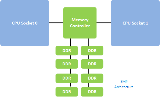
Quick Look: vCenter 5 Virtual Appliance

New with vSphere5 is an all new SUSE Linux-based (SLES11) virtual appliance to optionally run vCenter. The Windows-based counterpart is still available, of course. DB2 provides the embedded backend of the vCenter vApp with remote data support provided for the Oracle DBMS only, no SQL server (yet).  Despite the list of limits with this version (outlined below), the vCenter vApp is a very compelling option that introduces great simplicity and cost savings to your overall vSphere solution. The SUSE and DB2 licenses come free of charge but you will still need a vCenter license so you can save on the Windows Server and potentially SQL Server licenses. The embedded DB2 database can support up to 400 hosts or 4000 VMs provided you give the vApp enough RAM. There are currently a few important limitations of the vApp, as identified by Duncan Epping of VMware, that could make it a deal breaker for you:

  • No Update Manager
  • No Linked-Mode
  • No support for the VSA (vSphere Storage Appliance)
  • Only support for Oracle as the external database
  • No support for vCenter Heartbeat

To get started you will need 3 files: the system VMDK, the data VMDK, and the OVF file. These can be downloaded from VMware under the vSphere5 components for vCenter.

Connect to an ESXi host directly via the vSphere Client and deploy the OVF template.

Review the details of the vApp then define the name and location.

Next select the disk format. You will notice that vSphere 5 has some new provisioning options here for thick disks: Lazy and Eager zeroed. Lazy zeroed has all space allocated at the time of creation, but each block is zeroed only on the first write. This reduces creation time but also reduces performance of blocks only the first time they are written to. Eager zeroed has all space allocated and zeroed at the time of creation. This increases disk creation time but also increases performance of all block writes. The eager method is more of a “true” thick provisioning in the classic sense while lazy is more of a hybrid of thick and thin.

image

Once all selections are made, you are off to the races. Deployment can take several minutes to complete.

By default the vCenter vApp is configured with 8GB vRAM and 2 single core vCPUs, the configuration of which is another new feature in vSphere5.

Once the VM is powered on you will come to the following console screen that details how to connect. Initial vCenter configuration is done via web browser on port 5480.

Once connected via web browser, the initial login is root\vmware.

Before you get started, accept the EULA and check for any updates to the appliance via the update tab.

There are a few additional configuration items to address before vCenter will be usable. The first of which is defining the database settings. You can choose to use the embedded DB2 database or specify an external Oracle server. Make your selection and save the settings.

Next, select the inventory size you intend to work with. As you can see in the following screenshot, a setting of “large” equates to 400 hosts or 4000 VMs and will require a minimum of 17GB of vRAM for vCenter.

With those items checked, you should now be able to start the vCenter service.

Before you leave the web configurator, it might be prudent to set a static IP and configure Active Directory integration as well. Now you should be able to connect to vCenter via the vSphere client. vCenter itself is still the familiar interface that you would expect. Functionally, besides the few missing items, there is no difference between this Linux-based vApp and its Windows counterpart. 3rd-party plugin/ addon support may vary in the vApp model.

The vApp performance overall is quite good and there is no issue moving it between hosts in its cluster. Assuming feature integration continues and the gap between this appliance and the Windows solution is narrowed, it makes sense that the vApp may one day be the only offering for vCenter. There are quite a few other things that must happen first, however, namely the View component integration requirements. There is still an awful lot in VMware’s overall product offering that relies on Windows and that OS’ integrated technologies. I definitely recommend that you give the vCenter vApp a spin and see if it is a good fit for your organization.