Dell EMC ScaleIO – Scale and Performance for Citrix XenServer

You’ll be hearing a lot more about Dell EMC ScaleIO in the coming months and years. ScaleIo is a Software Defined Storage solution from Dell EMC that boasts massive flexibility, scalability and performance potential. It can run on nearly any hardware configuration from any vendor, all-flash or spinning disk, as well as supports XenServer, Linux and VMware vSphere. Like most other SDS solutions, ScaleIO requires a minimum of three nodes to build a cluster but unlike most others, ScaleIO can scale to over 1000 nodes in a single contiguous cluster. ScaleIO uses a parallel IO technology that makes active use of all disks in the cluster at all times to process IO. This performance potential increases as you scale and add nodes with additional disks to the cluster. This translates to every VM within the cluster being able to leverage the entire available performance profile of every disk within the cluster. Limits can be imposed, of course, to prevent any single consumer from draining all available IO but the greater potential is immense.


Key Features

  • Tiering – Unlike most SDS offers available, ScaleIO requires no tiering. For an all-flash configuration, every SSD in every node is completely usable. DAS Cache is required on hybrid models for write-back caching. It should also be noted that for hybrid configurations, each disk type must be assigned to separate volumes. There is no mechanism to move data from SSD to HDD automatically.
  • Scalability – 3 nodes are required to get started and the cluster can scale to over 1000 nodes.
  • Flexibility – Software solution that supports all hardware, all major hypervisors. Able to be deployed hyper-converged or storage only.
  • Data protection – two-copy mirror mesh architecture eliminates single points of failure.
  • Enterprise features – QOS, thin provisioning, snapshotting.
  • Performance – Parallel IO architecture eliminates disk bottlenecks by using every disk available in the cluster 100% of the time. The bigger you scale, the more disks you have contributing capacity and parallel IO. This is the ScaleIO killer feature.


ScaleIO Architecture

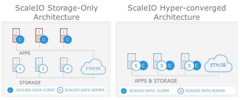
ScaleIO can be configured in an all-combined Hyper-converged Infrastructure (HCI) model or in a traditional distributed storage model. The HCI variant installs all component roles on every node in the cluster with any being able to host VMs. The distributed storage model installs the server pieces on dedicated infrastructure utilized for presenting storage only. The client consumer pieces are then installed on separate compute-only infrastructure. This model offers the ability to scale storage and compute completely separately if desired. For this post I’ll be focusing on the the HCI model using Citrix XenServer. XenServer is a free to use open source hypervisor with a paid support option. It doesn’t get much easier than this with XenServer running on each node and XenCenter running on the admin device of your choosing. There is no additional management infrastructure required! ScaleIO is licensed via a simple $/TB model but too can be used in trial mode.


The following are the primary components that comprise the ScaleIO architecture:

  • ScaleIO Data Client (SDC) – Block device driver that runs on the same server instance as the consuming application, in this case VMs. In the HCI model all nodes will run the SDC.
  • ScaleIO Data Server (SDS) – Not to be confused with the general industry term SDS, “SDS” in the ScaleIO context is a server role installed on nodes that contribute storage to the cluster. The SDS performs IOs at the request of the SDCs. In the HCI model all nodes will run the SDS role.
  • Metadata Manager (MDM) – Very important role! The MDM manages the device mappings, volumes, snapshots, storage capacity, errors and failures. MDM also monitors the state of the storage system and initiates rebalances or rebuilds as required.
    • The MDM communicates asynchronously with the SDC and SDS services via a separate data path so to not affect their performance.
    • ScaleIO requires at least 3 instances of the MDM: Master, Slave and Tie-Breaker.
    • A maximum of 5 MDM roles can be installed within a single cluster: 3 x MDMs + 2 x tie-breakers.
    • Only one MDM Master is active at any time within a cluster. The other roles are passive unless a failure occurs.
  • ScaleIO Gateway – This role includes Installation Manager for initial setup as well as the REST Gateway and SNMP trap sender. The Gateway can be installed on the ScaleIO cluster nodes or an external management node.
    • If the gateway is installed on a Linux server, it can only be used to deploy ScaleIO to Linux hosts.
    • If the gateway is installed on a Windows server, it can be used to deploy ScaleIO to Linux or Windows hosts.
    • XenServer, based on CentOS, fully qualifies as a “Linux host”.


Once the ScaleIO cluster is configured, all disks on each host are assigned to the SDS local to that host. Finally volumes are created and mounted as consumable to applications within the cluster.


The diagram below illustrates the relationship of the SDC and SDS roles in the HCI configuration:


My Lab Environment:

  • 3 x Dell PowerEdge R630
    • Dual Intel E5-2698v4
    • 512GB RAM
    • 480GB Boot SSD
    • 4 x 400GB SSDs
    • 5 x 1TB (7.2K RPM)
    • 2 x 10Gb NICs
  • XenServer 6.5
  • ScaleIO 2.0
  • XenDesktop 7.11
  • I also used a separate Windows server on an old R610 for my ScaleIO Gateway/ Installation Manager


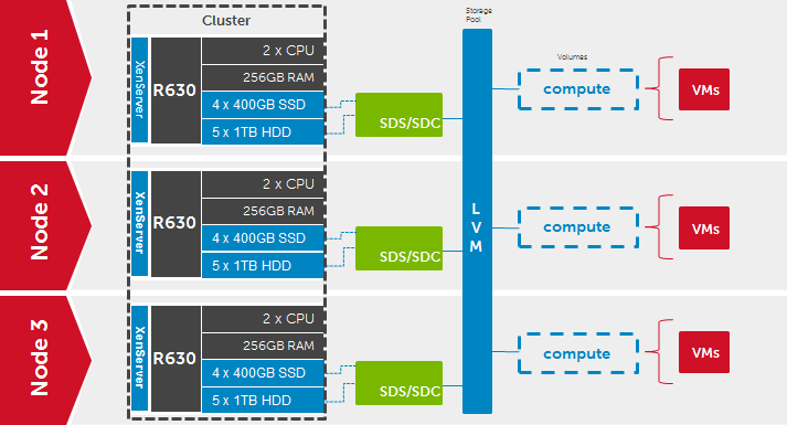
Here is the high-level architecture of my deployment. Note that there is a single compute volume which is mounted locally on each host via the XenServer Pool, so depicted below as logical on each:


Prep

As of this writing, XenServer 7.0 is shipping but 6.5 is the currently supported version by ScaleIO. The deployment steps for 7.0 should be very similar once officially supported. First install XenServer on each node, install XenCenter on your PC or management server, create a new pool, add all nodes to XenCenter, create a pool and fully patch each node with the XenCenter integrated utility. If the disks installed in your nodes have any prior formatting this needs to be removed in the PERC BIOS or via the fdisk utility within XenServer.

Now would be a good time to increase the memory available to Dom0 to the maximum 4GB, especially if you plan to run more than 50 VMs per node. From an SSH session or local command shell, execute:

/opt/xensource/libexec/xen-cmdline --set-xen dom0_mem=4096M,max:4096M


Install the packages required for ScaleIO on each node: numactl and libaio. OpenSSL needs to be updated to 1.0.1 using the XenCenter update utility via Hotfix XS65ESP1022.

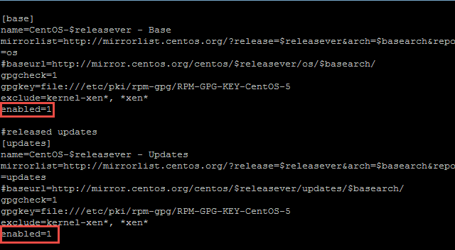
Libaio should already be present but before numactl can be added, the repositories will need to be edited. Open the base repository configuration file:

vi /etc/yum.repos.d/CentOS-Base.repo

Enable the Base and released updates repositories changing “enabled=0” to “enabled=1”. Save the file, :wq


Next install numactl, libaio should report as already installed, nothing to do. Repeat this on each node.

yum install numactl


ScaleIO Installation

Download all the required ScaleIO files: Gateway for Windows or Linux, as well as all the installation packages for ScaleIO (SDC, SDS, MDM, xcache, and lia). Install the ScaleIO Gateway files, either for Windows to do an external remote deployment, or for Linux to install the gateway on one of the XenServer nodes. For this installation I used an external Windows server to conduct my deployment. The ScaleIO Gateway installation for Windows has two prerequisites which must be installed first:

  • Java JRE
  • Microsoft Visual C++ 2010 x64 Redist

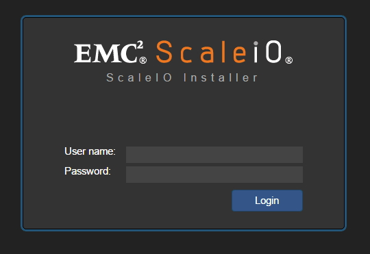
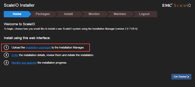
Next run the gateway MSI which will create a local web instance used for the remainder of the setup process. Once complete, in the local browser connect to https://localhost/login.jsp, and login using admin plus the password you specified during the Gateway setup. 


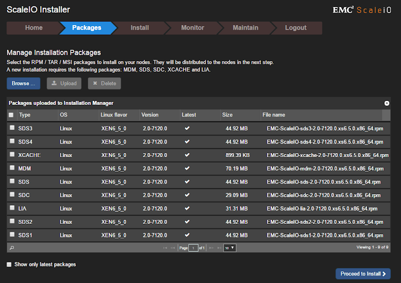
Once logged in, browse to and upload the XenServer installation packages to the Installation Manager (installed with the Gateway).


Here you can see that I have the ScaleIO installation packages for Xen 6.5 specifically.


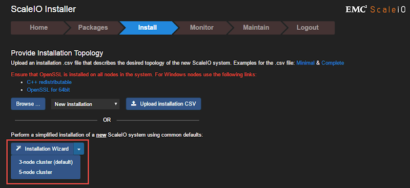
Once ready to install, you will be presented with options to either upload an installation CSV file, easier for large deployments, or if just getting started you can select the installation wizard for 3 or 5-node clusters. I will be selecting the wizard for 3-nodes.


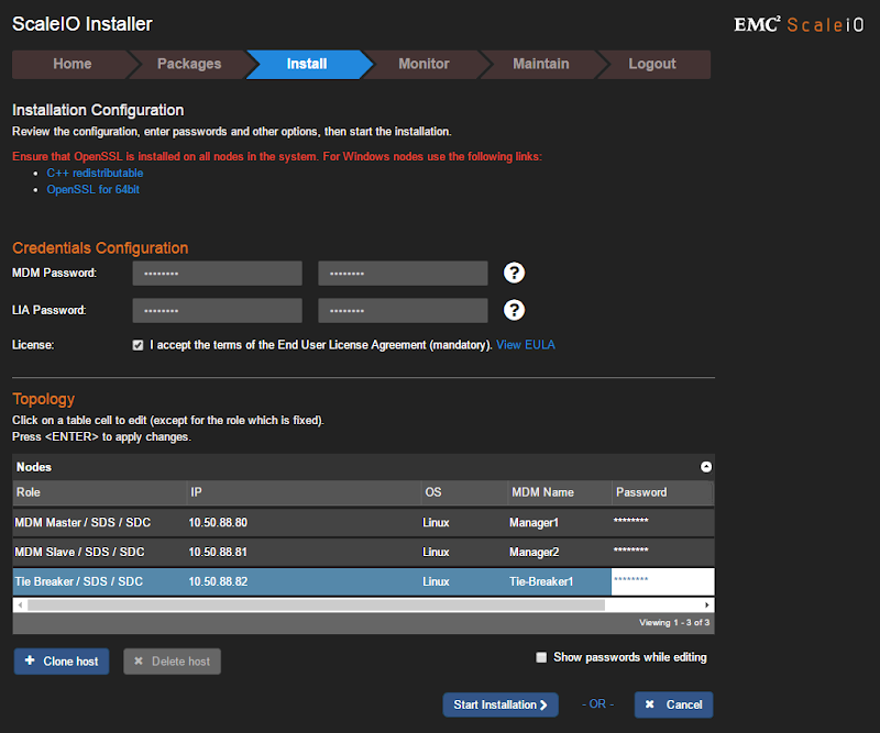
Specify the passwords for MDM and LIA, accept the EULA, then enter IP addresses and passwords for the mandatory three MDM instances at the bottom. The IP addresses at the bottom should be those of your physical XenServer nodes. Once all information is properly entered, the Start Installation button will become clickable. If you did not install the 1.0.1 OpenSSL patch earlier, this step will FAIL.


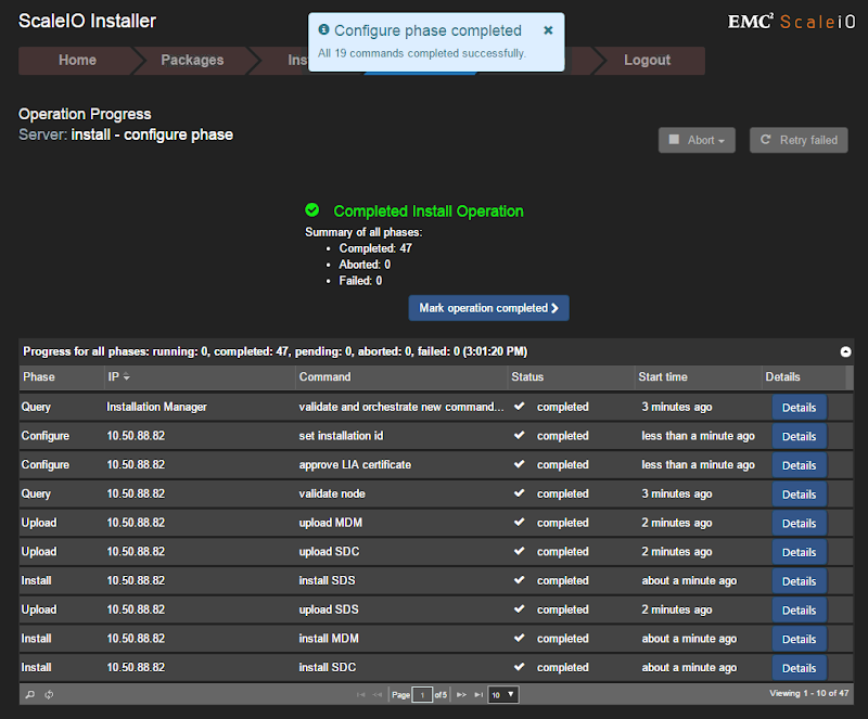
Several phases will follow (query, upload, install, configure) which should be initiated and monitored from the Monitor tab. You will be prompted to start the following phase assuming there were no failures during the current phase. Once all steps complete successfully, the operation will report as successful and can be marked as complete.


ScaleIO Configuration

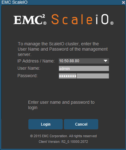
Next install then open the ScaleIO GUI on your mgmt server or workstation and connect to master MDM node configured previously. The rest of the configuration steps will be carried out here.


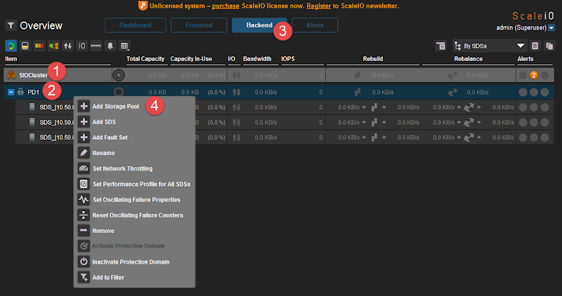
First thing, from the Backend tab, rename your default system and Protection Domain names to something of your choosing. Then create a new storage pool or rename the default pool.


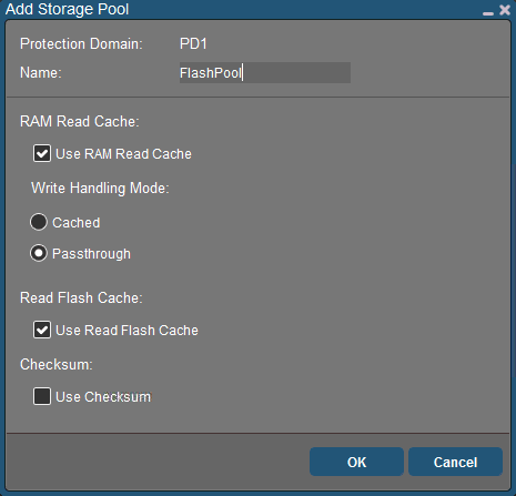
I’m naming my pools based on the disk media, flash and spinning. Create the pool within the Protection Domain, give it a name and select the caching options as appropriate.


Before we can build volumes we need to assign each disk to each SDS instance running on each node. First identify the disk device names on each host via SSH or local command shell by running:

fdisk -l


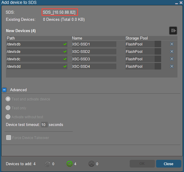
Each device will be listed as /dev/sdx. Right-click the first SDS on the first node and select Add Device. In the dialog that follows, add each local disk on this node, assign it to the appropriate pool and name it something meaningfully unique. If your disk add operation fails here, you probably have previous formatting on your disks which needs to be removed first using fdisk or the PERC BIOS! You can add both SSD and HDD devices as part of this operation.


Once this has been successfully completed for each node, you will see all disks assigned to each SDS in the GUI along with the total capacity contributed by each. You’ll notice that the circular disk icons next to each line are empty, because so are the disks at the moment.


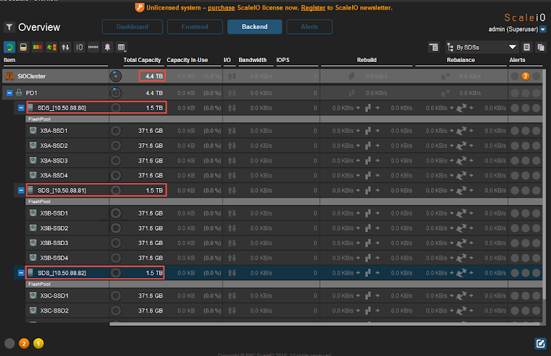
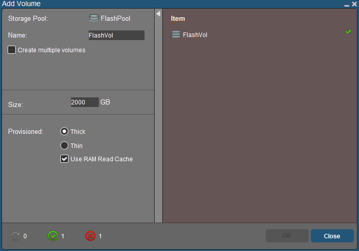
Now keep in mind that ScaleIO is a mirror mesh architecture, so only half of that 4.4TB capacity is usable. From the Frontend tab, right-click the Storage Pool and create a new volume with this in mind. I’m using thick provisioning here for the sake of simplicity.


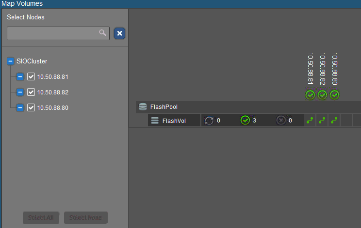
Once the volume is created, map it to each SDC which will make it available as a new disk device on each node. Right-click the volume you just created and select Map Volumes. Select all hosts then map volumes.


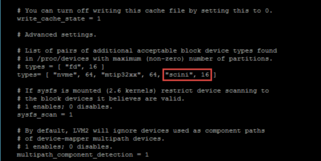
If you run fdisk -l  now, you will see a new device called /dev/scinia. The final step required before we can use our new storage is mounting this new device on each host which only needs to be done once if your hosts are configured in a Pool. By default the XenServer LVM is filtering so does not see our ScaleIO devices called “scini”. Edit the lvm configuration file and add this device type as highlighted below. Pay particular care to the text formatting here or LVM will continue to ignore your new volumes.

vi /etc/lvm/lvm.conf


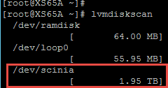
Next confirm that LVM can see the new ScaleIO device on each node, run:

lvmdiskscan


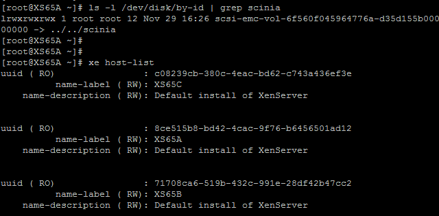
Now it’s time to create the XenServer Storage Repository (SR). Identify the UUIDs of the ScaleIO volumes presented to a host and identify the UUID of the host itself, just pick a host from the pool to work with. You will need the output of both of these commands when we create the SR.

ls -l /dev/disk/by-id | scini

xe host-list


This next part is critical! Because ScaleIO presents storage as a block device, specifically as an LVM, all thin provisioning support will be absent. This means that all VMs deployed in this environment will be full thick clones only. You can thin provision on the ScaleIO backend but all blocks must be allocated to your provisioned VMs. This may or may not work for your scenario but for those of you paying attention, this knowledge is your reward. 🙂 

Another very important consideration is that you need to change the “name-label” value for every SR you create. XenServer will allow you to create duplicate entries leaving you to guess which is which later! Change the portions in red below to match your environment.

xe sr-create content-type="ScaleIO" host-uuid=8ce515b8-bd42-4cac-9f76-b6456501ad12 type=LVM device-config:device=/dev/disk/by-id/scsi-emc-vol-6f560f045964776a-d35d155b00000000 shared=true name-label="SIO_FlashVol"


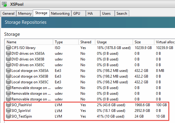
This command will give no response if successful, only an error if it wasn’t. Verify that the volumes are now present by looking at the Pool storage tab in XenCenter. Creating this SR on one host will enable access to all within the pool.


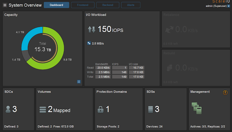
Now the disk resources are usable and we can confirm on the ScaleIO side of things by going back to the dashboard in the ScaleIO GUI. Here we can see the total amount of raw storage in this cluster, 15.3TB, the spare amount is listed in blue (4.1TB), the thin yellow band is the volume capacity with the thicker green band behind it showing the protected capacity. Because I’m using thick volumes here, I only have 1.4TB unused. The rest of the information displayed here should be self-explanatory.


ScaleIO & XenDesktop

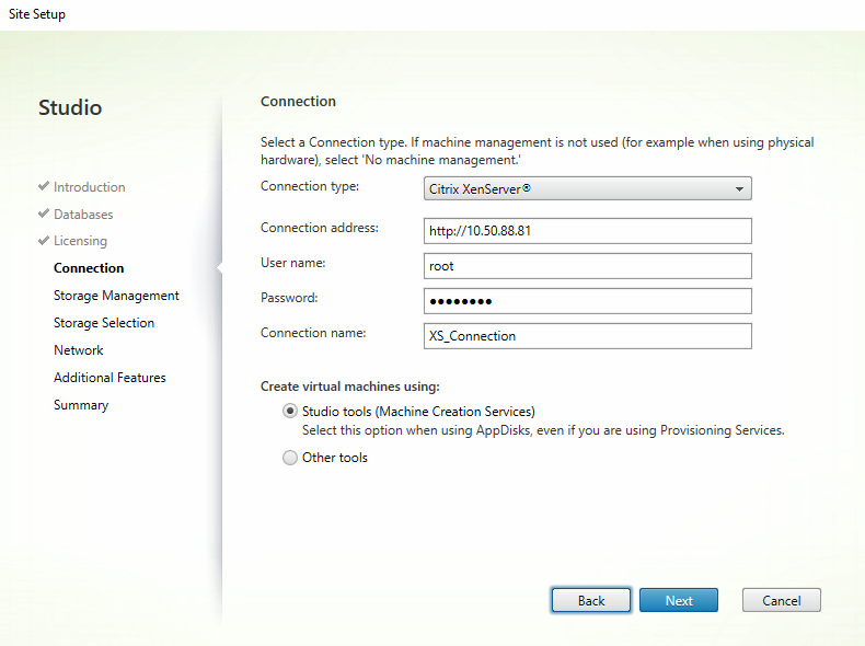
Since we’re talking about Citrix here, I would be remiss if I didn’t mention how XenDesktop works in a ScaleIO environment. The setup is fairly straight-forward and since we’re using XenServer as the hypervisor, there is no middle management layer like vCenter or SCVMM. XenDesktop talks directly to XenServer for provisioning, which is awesome.


If running a hybrid configuration, you can separate OS and Temporary files from PvDs, if desired. Here I’ve placed my PvD’s on my less expensive spinning volume. It’s important to note that Intellicache will not work with this architecture!


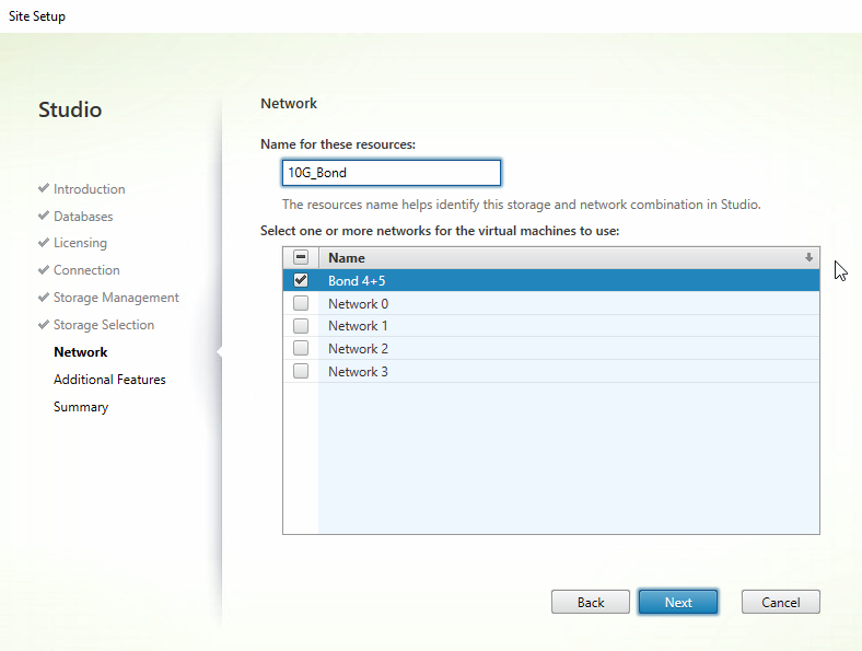
Select the VM network which should be a bond of at least 2 NICs that you created within your XenServer Pool. If you haven’t done this yet now would be a good time.


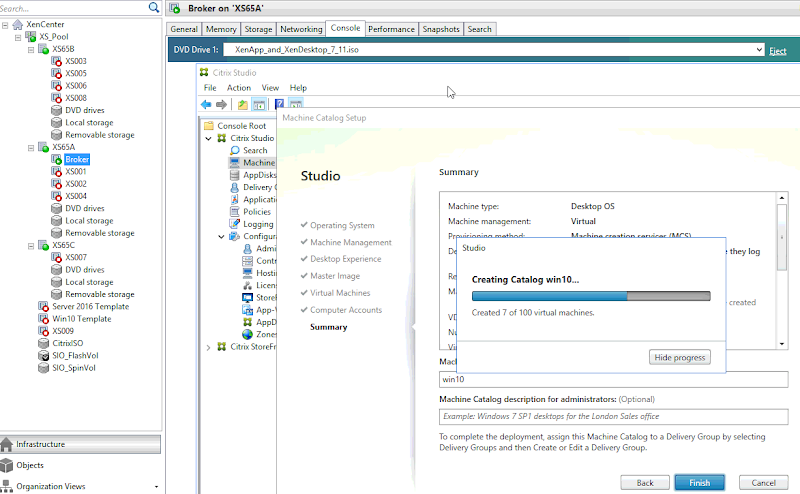
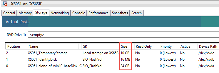
Finish the setup process then build a machine catalog using a gold master VM that you configured and shut down previously. I’ve configured this catalog for 100 VMs with 2GB RAM and 10GB disk cache. The gold master VM has a disk size of 24GB. Here you can see my catalog being built and VMs are being created on each host in my pool.


This is where things get a bit…sticky. Because ScaleIO is a block device, XenServer does not support the use of thin provisioning, as mentioned earlier. What this means is that the disk saving benefits of non-persistent VDI will be absent as well. Each disk image, PvD and temporary storage allocated to each VM in your catalog will consume the full allotment of its assignment.  This may or may not be a deal breaker for you. The only way to get thin provisioning within XenServer & XenDesktop is by using shared storage presented as NFS or volumes presented as EXT3, which in this mix of ingredients, applies to local disk only. In short, if you choose to deploy VDI on ScaleIO using XenServer, you will have to use thick clones for all VMs.


Performance

Lastly, a quick note on performance, which I tested using the Diskspd utility from Microsoft. You can get very granular with diskspd to model your workload, if you know the characteristics. I ran the following command to model 4K blocks weighted at 70% random writes using 4 threads, cache enabled, with latency captured.

Diskspd.exe -b4k -d60 -L -o2 -t4 -r -w70 -c500M c:\io.dat


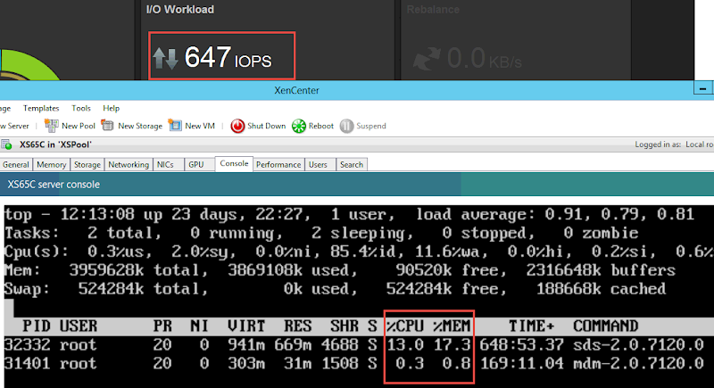
Here’s the output of that command real time from the ScaleIO viewpoint to illustrate performance against the SSD tier. Keep in mind this is all being generated from a single VM, all disks in the entire cluster are active. You might notice the capacity layout is different in the screenshot below, I reconfigured my protection domain to use thin provisioning vs thick when I ran this test.


Here is a look at the ScaleIO management component resource consumption during a diskspd test against the spinning tier generated from a single VM. Clearly the SDS role is the busiest and this will be the case across all nodes in the cluster. The SDC doesn’t generate enough load to make it into Top plus it changes its PID every second.


Closing

There are a lot of awesome HCI options in the market right now, many from Dell EMC. The questions you should be asking are: Does the HCI solution support the hypervisor I want to run? Does the HCI solution provide flexibility of hardware I want to run? And, is the HCI solution cost effective? ScaleIO might be perfect for your use case or maybe one of our solutions based on Nutanix or VSAN might be better suited. ScaleIO and XenServer can provide a massively scalable, massively flexible solution at a massively competitive price point. Keep in mind the rules on usable disk and thin provisioning when you go through your sizing exercise.


Resources

XenServer Hotfixes

Configure Dom0 memory

ScaleIO Installation Guide

ScaleIO User Guide

Moving a Nutanix Hyper-V Cluster between Domains


So you have a shiny 4-node Server 2012 R2 Hyper-V Failover Cluster running on Nutanix humming along no problem. Sadly, you only have a single virtual domain controller hosted somewhere else that owns the AD for your severs and failover cluster. Crap, someone deleted the DC! Well, you wanted to move this cluster to your primary domain anyway, guess now you have an excuse. This is probably a very rare scenario but should you be unlucky enough to have it happen to you, here is how to deal with it. All of this took place on my 4-node Nutanix cluster which is honestly inconsequential, but goes to show that the Nutanix storage cluster itself was entirely unaffected and frankly unconcerned by what I was doing. The same basic steps in this post would apply assuming your VMs are on stable, well-connected, shared storage.

In this scenario, there are really 2 ways to go:

Option A: start over, rebuild your hosts
Some might opt for this and as long as you don’t have data that needs preserving, go for it. In my case I have CVMs and VMs on every host, not interested.

Option B: change domains, rebuild the Failover Cluster, migrate VMs
This might seem messy but since I have data I need to save, this is the route I’ll be going. This scenario assumes that networking was functioning prior to the migration and that it will remain the same. Adding IP, vSwitch or other network changes to this could really complicate things and is not recommend.

Core or GUI

If you’re a PowerShell master then staying in Core mode may not be an issue for you. If you’re not, you might want to convert your Server Core instance to full GUI mode first, if it isn’t there already. I wrote about how to do that here. While you’re at it, make sure all nodes are at exactly the same Windows patch level.

Out with the old

I’ll be transitioning 4 active nodes from a dead and gone domain named test1.com to my active domain dvs.com. First, power off all VMs and remove their association from the old cluster. We’re not touching the storage here so there will be no data loss.
image

Migration of each node will occur one at a time by first evicting the node to be converted from the old cluster. Important: do this BEFORE you change domains!
image

If, and only if, this is the last and final node you will be migrating, you can now safely destroy the old failover cluster. Do this only on the very last node!
SNAGHTMLf08207b

Once a node is ready to make the switch, change the host’s DNS entries to point to the DCs of the domain you will be migrating to, then join the new domain.
image

In with the new

Once your first node is back up, create a new failover cluster. I’m reusing the same IP that was assigned to the old cluster to keep things simple.  Since this is Nutanix which manages its own storage, there are no disks to be managed by the failover cluster, so don’t import anything. Nothing bad will happen if you do, but Hyper-V doesn’t manage these disks so there’s no point. Also, if you run the cluster suitability checks they will fail on the shared storage piece.
image

Repeat this process for each node to be migrated, adding each to the new cluster. Next import your pre-existing VMs into the new cluster and configure them for high availability.
image

In Prism, just for good measure, update the FQDN in cluster details:
image

Let the Distributed Storage Fabric settle. Once the CVMs are happy, upgrade the NOS if desired.
image

Pretty easy if you do things in the right order. Here is a view of Prism with my 4 hosts converted and only CVMs running. Definitely not a busy cluster at the moment but it is a happy cluster ready for tougher tasks!
image

If things go badly

Maybe you pulled the trigger on the domain switch first before you evicted nodes and destroyed the cluster? If so, any commands directed at the old cluster to the old domain will likely fail with access being denied. You will be prevented from removing the node or destroying the old cluster.
image

If this happens you’ll need to manually remove & restore the cluster services on that node. Since none of the Cmdlets are working it’s time to turn to the registry. Find “ClusDisk” and “ClusSVC” keys within the following path and delete them both. You’ll see entries reflecting the old cluster and old configuration:

HKLM\System\CurrentControlSet\Services\

image

Now you can remove the Failover Clustering feature from the Remove Roles and Features wizard:
image

Reboot the host and install the Failover Clustering feature again. This will set the host back to square one from a clustering perspective, so you can now create a new cluster or join one preexisting.

For more information…

Forcibly removing clustering features
Dell XC Web-scale Appliance Architectures for VDI
Dell XC Web-Scale Converged Appliances
nutanix.com

Fun with the Dell Chromebook 13

chrome-logo

I’ve been fortunate enough to acquire a shiny new Dell Chromebook 13 (7310) which is winning accolades everywhere in the Chrome universe.  Intel i5-5300U (Broadwell), 8GB RAM, 32GB SSD, 1080p display, amazing battery life… this thing is an absolute beast and light as a feather to boot. ChromeOs as expected is a minimal Google-centric affair centered entirely around the Chrome browser and apps available in the Chrome store. This is not Android, this is Chrome. For many this type of platform would work great providing speedy web browsing, games, office docs and connectors to your corporate VDI desktop. This solution is an obvious fit for the EDU space where Chrome is a BIG market. I’m starting to think that a Chromebook is really what my parents and technically-challenged in-laws need. It’s just dead simple and provides all the functionality they could need.

image

But, as you know, I can’t just leave well enough alone. There is so much hardware performance prowess here that begs for me to tap into it. Naturally the 2nd thing I had to do was install Linux so I can do all the things I can’t do in Chome, namely run Steam to ultimately play Dota2 and Minecraft. YES!

Everything that follows is NOT supported by Dell nor Google, will probably void your warranty and may cause your precious Chromebook to burst into flames (not really). Anything bad that happens to you will not be my fault. I’m documenting this for my own selfish intentions of information preservation. Proceed at your own risk or peril!


ChromeOS is powered via a Linux kernel so outfitting to work with a separate Linux distro is not a terribly difficult task and frankly a match made in heaven. 32GB is plenty of room to run a minimal Linux instance and your choice of desktop plus a game title or two. There are a couple of ways to go here but one of the easiest and most popular is using crouton which is ultimately a chroot generator for ChromeOS. Crouton provides the ability to run Ubuntu on the Chromebook leveraging the existing ChromeOS kernel so you can leave your existing ChromeOS instance in place. Normally, you would be able to switch back and forth between the operating environments real-time so you get the best of both worlds here, but this appears to be broken for me at the moment. I can play in one environment or the other, no biggie. The following are the steps I took to create a Linux environment on my Chromebook so I could run Steam and play Dota.

Create ChromeOS Recovery Disk

As is always the best practice, take a backup of your perfectly working Chromebook before you make any changes. To do this, first install the Chromebook Recovery Utility on the Chromebook. Insert a USB stick that is 4GB or larger, follow the prompts. Easy peasy.

image


Enable Developer Mode

The first step on our journey is to enable developer mode. This removes the security of OS verification and will warn you every time the device is restarted. To enable this mode hold down ESC and Refresh keys then tap the power button to enter recovery. Once there you will see this somewhat scary and currently inaccurate screen:

image


Press Ctrl + D to enter developer mode, confirm then reboot. This operation will wipe your device so plan accordingly! Once complete you will see the following screen initially at every reboot which can be bypassed with Ctrl+D or you can wait for it to time out.

image


Once the system comes back up, go through the initial setup process again to get into Chrome and connected to the network.


Install Crouton

From Chrome, Grab the latest crouton file: https://goo.gl/fd3zc and save to the Downloads folder.

In Chrome, press Ctrl+Alt+T to open a crosh terminal tab within the browser. Type “shell” to enter the Linux shell mode:

image


Next, install crouton by executing:

sudo sh -e ~/Downloads/crouton -t xfce

If this fails due to a lack of permissions, then execute the following to first gain root:

sudo su

Run the command again without sudo and point to the crouton file within your user profile. Keep in mind that you’ll be running as root now and “~Downloads” will not have your crouton file. You will need to navigate to or point sh at this specific directory so the command will execute correctly. In this example the required command would be:

sh -e /home/user/b4b68a7dfa3e92f1f0f371473c58f9bf2de97424/Downloads/crouton -t xfce


image

This will install the crouton chroot with ubuntu and the xfce desktop, which is a very lightweight GUI. You can optionally install Unity if you want something “heavier”.  Substitute unity at the end of the command instead of xfce.

While you’re at this step, install the crouton integration extension for Chrome which will provide handy functionality like clipboard synchronization between environments: link

This will take some time to complete and once it does, start your crouton session so you can enter the Linux desktop, execute:

sudo startxfce4

This will run a series of scripts then take you to your fresh new Linux desktop UI. This command will need to be run in crosh every time you reboot or log off from within Ubuntu.

xfce


Update Ubuntu

This step is optional but if you want the latest or newer build, or to clean up the packages crouton included by default, it’s a good idea to update. There are a couple of ways to do this but the easiest is via Ubuntu’s Software Updater. From the Terminal , execute:

sudo apt-get install update-manager synaptic

This will install the Ubuntu updater as well as the Synaptic Package Manager. Run the Software Updater and install Ubuntu 14.04 trusty which will take a while. You will be prompted to remove old packages, do this. Once complete you will be prompted to reboot. Enter the crosh shell again and update the crouton config (precise is the name of my chroot):

sudo sh ~/Downloads/crouton -u –n precise

You can check the version of crouton installed vs what is available online by running:

croutonversion -u -d -c

Run sudo startxfce4 and you’ll be back to the Linux desktop. One more step before we can install Steam.

Update Intel Drivers

This is a core i5-5300U system which has a damn decent on-die HD 5500 GPU, but at this point in my build I have no OpenGL drivers yet. If you installed Steam and tried to launch Dota you would see an error about the GPU lacking support for OpenGL 3.1. Run the following extremely long command to perform a thorough update of the Intel parts within your system:

sudo apt-get install --install-recommends xserver-xorg-lts-utopic libqt5gui5 libgles1-mesa-lts-utopic libgles2-mesa-lts-utopic libgl1-mesa-glx-lts-utopic libgl1-mesa-glx-lts-utopic:i386 libglapi-mesa-lts-utopic:i386 libegl1-mesa-drivers-lts-utopic

Remap Volume and Brightness Keys

The top row of keys all have a specific purpose and directly map to F1, F2, etc on a regular keyboard, they are merely obscured here. Once your Linux environment is installed some of these keys won’t work, namely the volume and screen brightness controls. To fix this open the keyboard application and select the Application Shortcuts tab. Add a new command for each key you want to map as shown below then choose the corresponding key.

amixer set Master 10%+ (Volume up key/ F10)

amixer set Master 10%- (Volume down key/ F9)


amixer set Master toggle (mute key/ F8)


brightness down (small sun key/ F6)


brightness up (large sun key/ F7)

keys

Install Chrome for Linux

Netsurf, the default xfce browser, is a very, very basic browser which may suit your needs just fine. If you need to access any site that uses javascript, however, it will not be able to render as there is no support. Save yourself pain and just install Chrome from the jump. The following commands will add the key, set the repository and install the Chrome package:

wget -q -O - https://dl-ssl.google.com/linux/linux_signing_key.pub | sudo apt-key add - 
sudo sh -c 'echo "deb http://dl.google.com/linux/chrome/deb/ stable main" >> /etc/apt/sources.list.d/google.list'
sudo apt-get update 
sudo apt-get install google-chrome-stable

Install Steam, Install Dota2

At this point you should be in very good shape and ready to have fun. Installing Steam is straight-forward, download the Linux client from their site, install. Log in, install Dota. Now with 32GB there is enough space to install Steam and Dota locally, which is ~14GB. With everything, I still have ~8GB free space on the SSD. If you wanted to use the Chromebook to run more titles or simply don’t want to install the games locally, there is a method to install to an external SD card. See the links in the resources section at the bottom to learn how.  The graphics performance is actually quite good considering there is no discrete GPU present. Dota video settings notched up 1 level from the bottom performs quite well. Fallout4? Probably not so much.

dota

Install Java, Install Minecraft

Minecraft requires the Java Runtime, so installing the JRE is step 1. The easiest way to do this is via a PPA (Personal Package Archive) which will download the required files from Oracle and install them. If you have any other package manager application running at the same time, this process may fail with an error about getting a lock on /var/lib/dpkg. Close Synaptic or Software Center first, then run the following commands in the Terminal:

sudo apt-get-repository ppa:webupd8team/java
sudo apt-get update
sudo apt-get install oracle-java8-installer

sudo apt-get install oracle-java8-set-default

Once Java is installed, browse to Minecraft.net and download minecraft.jar. This is the launcher that will download, update and run Minecraft. Keep this file and put it in a safe place. To run right away, in Terminal navigate to the directory of the jar file and run:

java -jar minecraft.net

The familiar launcher will appear where you can log in and play. You could run the previous command every time you want to play or create a shortcut script for easier launching. First create the sh file on your desktop (CD to your desktop) and enter (nano is not present in this build):

vi minecraft.net

With the Vi editor open to your new file, enter the following 3 lines and save (see the Vi cheat sheet link at the bottom if you need help):

#bin/bash
java -jar ~/Documents/Minecraft.jar
exit

Right-click the new sh file and on the Permissions tab check the box to “Allow this file to be run as a program”. Anytime you want to play Minecraft just double-click this file and off you go. Now we have a full fledged Minecraft install with all the privileges that affords including mods, maps and servers. The performance is fantastic on the Chromebook with absolutely zero lag whatsoever.

That’s all there is to it! Now my Chromebook is a very capable dual purpose machine that I can do almost anything I want. In previous versions of ChromeOS and crouton it was possible to seamlessly switch between ChromeOS and Linux by using the key combo Ctrl+alt+shift+forward (or backward). This doesn’t work for me right now with the ChromeOS side either appearing blank screen or frozen accepting no inputs. Others had this same problem earlier in the year so it appears that it may have never been resolved. If you know of a workaround please speak up in the comments! For now, to get to ChromeOS from Linux you have to reboot then start up your chroot again when ready. Not ideal but not a huge inconvenience either since your Linux sessions are saved and easily restored. In this build I have ChromeOS, Couton/ Ubuntu, Steam, Dota, Java and Minecraft all installed with 5.2GB to spare. Not bad! Not to mention that the graphics performance is better here using the Core i5 chip alone vs older laptops I have with discrete NVIDIA NVS GPUs. Really impressive. If you want a very capable lightweight laptop to run Linux and a few games, look no further than the Dell Chromebook 13!

Resources

Chromebook Recovery Utility

crouton

Crouton install walkthrough

Intel Driver Update

Map volume and brightness keys

Installing Dota on external SD card

Vi Cheat sheet

Dell XC730 – Graphics HCI Style

Our latest addition to the wildly popular Dell XC Web-Scale Converged Appliance series powered by Nutanix, is the XC730 for graphics. The XC730 is a 2U node outfitted with 1 or 2 NVIDIA GRID K1 or K2 cards suited for highly scalable and high-performance graphics within VDI deployments.  The platform supports either Hyper-V with RemoteFX or VMware vSphere 6 with NVIDIA GRID vGPU.  Citrix XenDesktop, VMware Horizon or Dell Wyse vWorkspace can be deployed on the platform and configured to run with the vGPU offering. Being a graphics platform, the XC730 currently supports up to 2 x 120w 10, 12, or 14-core Haswell CPUs with 16 or 32GB 2133MHz DIMMs. The platform requires a minimum of 2 SSDs and 4 HDDs with a range of options within each tier. All XC nodes come equipped with a 64GB SATADOM to boot the hypervisor and 128GB total spread across the first 2 SSDs for the Nutanix Home. Don’t know what mix of components to choose or how to size your environment? No problem, we create optimized platforms and validate them to make your life easier.


image

Optimized High Performance Graphics

Our validated platform for the XC730 is a high-end “B7” variant that provides the absolute pinnacle of graphics performance in an HCI offer. 14-core CPUs, 256GB RAM, dual K2’s, 2 x 400GB SSDs and 4 x 1TB HDDs. This is all about graphics so we need more wattage and the XC730 comes equipped with dual 1100w PSUs. iDRAC8 comes standard in the XC Series as well as your choice of 10Gb SFP+ or BaseT Ethernet adapters. I chose this mix of components to provide a very high-end experience to support the maximum number of users allowed by the K2 vGPU profiles. Watch this space for additional optimized platforms designed to remove the guess of sizing graphics in VDI. Even when GPUs are present, the basic laws of VDI exist which state: thou shalt exhaust CPU first. Dual 14-core parts will ensure that doesn’t happen. Make sure to check out our Appliance Architectures at the bottom of this post for more detailed info.


image


NVIDIA GRID vGPU

The cream of the crop in server virtualized graphics comes courtesy of NVIDIA with the K1 and K2 Kepler-based boards. The K2 has 4x the CUDA cores of the K1 board with a slightly lower core clock and less total memory. The K2 is the board you want for fewer higher end users. The K1 is appropriate for a higher overall number of lower end graphical users. vGPU is where the magic happens as graphics are hardware-accelerated to the virtual environment running within vSphere.  Each desktop VM within the vGPU environment runs a native set of the NVIDIA drivers and addresses a real slice of the server grade GPU. The graphic below from NVIDIA portrays this quite well.


image

(image courtesy of NVIDIA)


The magic of vGPU happens within the profiles that ultimately get assigned. Both K1 and K2 in conjunction with vGPU have a preset number of profiles that ultimately control the amount of graphics memory assigned to each desktop along with the total number of desktops that can be supported by each card. The profile pattern is K2xxx for K2 and K1xxx for K1, the smaller index identifying a great user density. The K280Q and K180Q are basically pass-through profiles where an entire physical GPU is passed through to a desktop VM. You’ll notice how the densities change per card and per GPU depending on how these profiles are assigned. Lower performance = greater densities with up to 64 total users possible on an XC730 with dual K1 cards. In the case of the K2, the maximum number of users possible on a single XC730 with dual cards is 32.


image

So how does it fit?

When designing a solution using the XC730, all of the normal Nutanix and XC rules apply including a minimum of 3 nodes in a cluster and a CVM running on every node. Since the XC730 is a graphics appliance it is recommended to have additional XC630s in the architecture to run the VDI infrastructure management VMs as well as for the users not requiring high-performance graphics. Nothing will stop you from running mgmt infa on your XC730 nodes but financial practicality will probably dictate that you use XC630s for this purpose. Scale of either is unlimited.


image


It is entirely acceptable (and expected) to mix XC730 and XC630 nodes within the same NDFS cluster. The boundaries you will need to draw will be around your vSphere HA clusters separating each function into a discrete cluster up to 64 nodes, as depicted below. This allows each discrete layer to scale independently while providing dedicated N+1 HA for each function. Due to the nature of graphics virtualization, vMotion is not currently supported neither is automated HA VM restarts when GPUs are attached. HA in this particular scenario would be cold should a node in the cluster fail. Using pooled desktops and mobilizing user data, this should only equate to a minor inconvenience worst case. 


image


As is the case with any Nutanix deployment, very large NDFS clusters can be created with multiple hypervisor pods created within a singular namespace. Below is an example depiction of a 30K user deployment within a single site. Each compute pod is composed of a theoretical maximum number of users within a VDI farm, serviced by a dedicated pair of mgmt nodes for each farm. Mgmt is separated into a discrete cluster for all farms and compute is separated per the HA maximum. This is a complicated architecture but demonstrates the capabilities of NDFS when designing for a very large scale use case.

image


This is just the tip of the iceberg! For more information on the XC series architecture, platforms, Nutanix, test results of our XC730 platform and more, please see our latest Appliance Architectures which include the XC730:

XC Series for Citrix

XC Series for VMware

XC Series for vWorkspace

Dell XC Series 2.0: Product Architectures

Following our launch of the new 13G-based XC series platform, I present our product architectures for the VDI-specific use cases. Of the platforms available, this use case is focused on the extremely powerful 1U XC630 with Haswell CPUs and 2133MHz RAM. We offer these appliances on both Server 2012 R2 Hyper-V and vSphere 5.5 U2 with Citrix XenDesktop, VMware Horizon View, or Dell vWorkspace.  All platform architectures have been optimized, configured for best performance and documented.
dn

Platforms

We have three platforms to choose from optimized around cost and performance, all being ultimately flexible should specific parameters need to change. The A5 model is the most cost effective leveraging 8-core CPUs, 256GB RAM 2 x 200GB SSDs for performance and 4 x 1TB HDDs for capacity.  For POCs, small deployments or light application virtualization, this platform is well suited. The B5 model steps up the performance by adding four cores per socket, increasing the RAM density to 384GB and doubling the performance tier to 2 x 400GB SSDs. This platform will provide the best bang for the buck on medium density deployments of light or medium level workloads. The B7 is the top of the line offering 16-core CPUs and a higher capacity tier of 6 x 1TB HDDs. For deployments requiring maximum density of knowledge or power user workloads, this is the platform for you.
image
At 1U with dual CPUs, 24 DIMM slots and 10 drive bays…loads of potential and flexibility!
image

Solution Architecture

Utilizing 3 platform hardware configurations, we are offering 3 VDI solutions on 2 hypervisors. Lots of flexibility and many options. 3 node cluster minimum is required with every node containing a Nutanix Controller VM (CVM) to handle all IO. The SATADOM is present for boot responsibilities to host the hypervisor as well as initial setup of the Nutanix Home area. The SSDs and NL SAS disks are passed through directly to each CVM which straddle the hypervisor and hardware. Every CVM contributes its directly-attached disks to the storage pool which is stretched across all nodes in the Nutanix Distributed File System (NDFS) cluster. NDFS is not dependent on the hypervisor for HA or clustering. Hyper-V cluster storage pools will present SMB version 3 to the hosts and vSphere clusters will be presented with NFS. Containers can be created within the storage pool to logically separate VMs based on function. These containers also provide isolation of configurable storage characteristics in the form of dedupe and compression. In other words, you can enable compression on your management VMs within their dedicated container, but not on your VDI desktops, also within their own container. The namespace is presented to the cluster in the form of \\NDFS_Cluster_name\container_name.
The first solution I’ll cover is Dell’s Wyse vWorkspace which supports either 2012 R2 Hyper-V or vSphere 5.5. For small deployments or POCs we offer this solution in a “floating mgmt” architecture which combines the vWorkspace infrastructure management roles and VDI desktops or shared session VMs. vWorkspace and Hyper-V enables a special technology for non-persistent/ shared image desktops called Hyper-V Catalyst which includes 2 components: HyperCache and HyperDeploy. Hyper-V Catalyst provides some incredible performance boosts and requires that the vWorkspace infrastructure components communicate directly with the hyper-V hypervisor. This also means that vWorkspace does not require SCVMM to perform provisioning tasks for non-persistent desktops!

  • HyperCache – Provides virtual desktop performance enhancement by caching parent VHDs in host RAM. Read requests are satisfied from cache including requests from all subsequent child VMs.
  • HyperDeploy – Provides instant cloning of parent VHDs massively diminishing virtual desktop pool deployment times.

You’ll notice the HyperCache components included on the Hyper-V architectures below. 3 to 6 hosts in the floating management model, depicted below with management, desktops and RDSH VMs logically separated only from a storage container perspective by function. The recommendation of 3-7 RDSH VMs is based our work optimizing around NUMA boundaries. I’ll dive deeper into that in an upcoming post. The B7 platform is used in the architectures below.
image
Above ~1000 users we recommend the traditional distributed management architecture to enable more predictable scaling and performance of both the compute and management hosts. The same basic architecture is the same and scales to the full extent supported by the hypervisor, is this case Hyper-V which supports up to 64 hosts. NDFS does not have a scaling limitation so several hypervisor clusters can be built within a single contiguous NDFS namespace. Our recommendation is to then build independent Failover Clusters for compute and management discretely so they can scale up or out independently.
The architecture below depicts a B7 build on Hyper-V applicable to Citrix XenDesktop or Wyse vWorkspace.
image

This architecture is relatively similar for Wyse vWorkspace or VMware Horizon View on vSphere 5.5 U2 but fewer total compute hosts per HA cluster, 32 total. For vWorkspace, Hyper-V Catalyst is not present in this scenario so vCenter is required to perform desktop provisioning tasks.
image
For the storage containers, the best practice of less is more still stands. If you don’t need a particular feature don’t enable it, as it will consume additional resources. Deduplication is always recommended on the performance tier since the primary OpLog lives on SSD and will always benefit. Dedupe or compression on the capacity tier is not recommended, of course you absolutely need it. And if you do prepare to increase each CVM RAM allocation to 32GB.

Container Purpose Replication Factor Perf Tier Deduplication Capacity Tier Deduplication Compression
Ds_compute Desktop VMs 2 Enabled Disabled Disabled
Ds_mgmt Mgmt Infra VMs 2 Enabled Disabled Disabled
Ds_rdsh RDSH Server VMs 2 Enabled Disabled Disabled

Network Architecture

As a hyperconverged appliance, the network architecture leverages the converged model. A pair of 10Gb NICs minimum in  each node handle all traffic for the hypervisor, guests and storage operations between CVMs. Remember that the storage of all VMs is kept local to the host to which the VM resides, so the only traffic that will traverse the network is LAN and replication. There is no need to isolate storage protocol traffic when using Nutanix. 
Hyper-V and vSphere are functionally similar. For Hyper-V there are 2 vSwitches per host, 1 external that aggregates all of the services of the host management OS as well as the vNICs for the connected VMs. The 10Gb NICs are connected to a LBFO team configured in Dynamic Mode. The CVM alone connects to a private internal vSwitch so it can communicate with the hypervisor.
image
In vSphere it’s the same story but with the concept of Port Groups and vMotion.
image
We have tested the various configurations per our standard processes and documented the performance results which can be found in the link below. These docs will be updated as we validate additional configurations.

Product Architectures for 13G XC launch:

Resources:

About Wyse vWorkspace HyperCache
About Wyse vWorkspace HyperDeploy
SJbWUYl4LRCwFNcatHuG

Dell XC Series Web-scale Converged Appliance 2.0

I am pleased to present the Dell XC 2.0 series of web-scale appliances based on the award-winning 13G PowerEdge server line from Dell. There’s lots more in store for the XC so just focusing on this part of the launch we are introducing the XC630 and the XC730xd appliances.

Flexibility and performance are key tenets of this launch providing not only a choice in 1U or 2U form factors, but an assortment of CPU and disk options. From a solution perspective, specifically around VDI, we are releasing three optimized and validated platforms with accompanied Product Architectures to help you plan and size your Dell XC deployments.

The basic architecture of the Dell XC powered by Nutanix remains the same. Every node is outfitted with a Nutanix Controller VM (CVM) that connects to a mix of SSD and HDD to contribute to a distributed storage pool that has no inherent scaling limitation. Three nodes minimum required and either VMware vSphere or Microsoft Windows Server 2012 R2 Hyper-V are supported hypervisors. Let’s take a look at the new models.

image

XC630

The XC630 is a 1U dual-socket platform that supports 6-core to 16-core CPUs and up to 24 x 2133MHz 16GB RDIMMs or 32GB LRDIMMs. The XC630 can be configured using all flash or using two tiers of storage which can consist of 2 to 4 x SSDs (200GB, 400GB or 800GB) and 4 to 8 x 1TB HDDs (2TB HDDs coming soon). Flexible! All flash nodes must have a minimum of 6 x SSDs while nodes with two storage tiers must have a minimum of two SSDs and four HDDs. All nodes have a minimum of 2 x 1Gb plus 2 x 10Gb SFP+ or BaseT Ethernet that can be augmented via an additional card.

New to the XC 2.0 series is a 64GB SATADOM that is used to boot each node. Each node is also outfitted with a 16GB SD card used for the purposes of initial deployment and recovery. The SSDs and HDDs that comprise the Nutanix Distributed File System (NDFS) storage pool are presented to each CVM via an on-board 1GB PERC H730 set in pass-through mode. Simple, powerful, flexible.

image


XC730xd

For deployments requiring a greater amount of cold tier data capacity, the XC730xd can provide up to 32TB raw per node. The XC730xd is a 2U dual-socket platform that supports 6-core to 16-core CPUs and up to 24 x 2133MHz 16GB RDIMMs or 32GB LRDIMMs. The XC730xd is provided with two chassis options: 24 x 2.5” disks or 12 x 3.5” disks. The 24-drive model requires the use of two tiers of storage which can consist of 2 to 4 x SSDs (200GB, 400GB or 800GB) and 4 to 22 x 1TB HDDs .The 12-drive model also requires two tiers of storage consisting of 2 to 4 x SSDs (200, 400GB or 800GB) and up to 10 x 4TB HDDs. All nodes have a minimum of 2 x 1Gb plus 2 x 10Gb SFP+ or BaseT Ethernet that can be augmented via an additional card.

The XC730xd platforms are also outfitted with a 64GB SATADOM that is used to boot the nodes. The 16GB SD card used for the purposes of initial deployment and recovery is present on these models as well. The SSDs and HDDs that comprise the Nutanix Distributed File System (NDFS) storage pool are presented to each CVM via an on-board 1GB PERC H730 set in pass-through mode. Simple, powerful, flexible.

12 drive option, hopefully the overlaps in the image below make sense:

image


24 drive option:

image


Nutanix Software Editions

All editions of the Nutanix software platform are available with variable lengths for support and maintenance.

image

This is just the beginning. Keep an eye out for additional platforms and offerings from the Dell + Nutanix partnership! Next up is the VDI product architectures based on the XC630. Stay tuned!!

http://www.dell.com/us/business/p/dell-xc-series/pd

Clustering Server 2012 R2 with iSCSI Storage

Yay, last post of 2014! Haven’t invested in the hyperconverged Software Defined Storage model yet? No problem, there’s still time. In the meanwhile, here is how to cluster Server 2012 R2 using tried and true EqualLogic iSCSI shared storage.

EQL Group Manager

First, prepare your storage array(s), by logging into EQL Group Manager. This post assumes that your basic array IP, access and security settings are in place.  Set up your local CHAP account to be used later. Your organization’s security access policies or requirements might dictate a different standard here.

SNAGHTML3b62e029

Create and assign an Access Policy to the VDS/VSS in Group Manager otherwise this volume will not be accessible. This will make subsequent steps easier when it’s time to configure ASM.image

Create some volumes in Group Manager now so you can connect your initiators easily in the next step. It’s a good idea to create your cluster quorum LUN now as well.

image


Host Network Configuration

First configure the interfaces you intend to use for iSCSI on your cluster nodes. Best practice says that you should limit your iSCSI traffic to a private Layer2 segment, not routed and only connecting to the devices that will participate in the fabric. This is no different from Fiber Channel in that regard, unless you are using a converged methodology and sharing your higher bandwidth NICs. If using Broadcom NICs you can choose Jumbo Frames or hardware offload, the larger frames will likely net a greater performance impact. Each host NIC used to access your storage targets should have a unique IP address able to access the network of those targets within the same private Layer2 segment. While these NICs can technically be teamed using the native Windows LBFO mechanism, best practice says that you shouldn’t, especially if you plan to use MPIO to load balance traffic. If your NICs will be shared (not dedicated to iSCSI alone) then LBFO teaming is supported in that configuration. To keep things clean and simple I’ll be using 4 NICs, 2 dedicated to LAN, 2 dedicated to iSCSI SAN. Both LAN and SAN connections are physically separated to their own switching fabrics as well, this is also a best practice.

image

MPIO – the manual method

First, start the MS iSCSI service, which you will be prompted to do, and check its status in PowerShell using get-service –name msiscsi.

image

Next, install MPIO using Install-WindowsFeature Multipath-IO

Once installed and your server has been rebooted, you can set additional options in PowerShell or via the MPIO dialog under  File and Storage Services—> Tools.

image

Open the MPIO settings and tick “add support for iSCSI devices” under Discover Multi-Paths. Reboot again. Any change you make here will ask you to reboot. Make all changes once so you only have to do this one time.

image

The easier way to do this from the onset is using the EqualLogic Host Integration Tools (HIT Kit) on your hosts. If you don’t want to use HIT for some reason, you can skip from here down to the “Connect to iSCSI Storage” section.

Install EQL HIT Kit (The Easier Method)

The EqualLogic HIT Kit will make it much easier to connect to your storage array as well as configure the MPIO DSM for the EQL arrays. Better integration, easier to optimize performance, better analytics. If there is a HIT Kit available for your chosen OS, you should absolutely install and use it. Fortunately there is indeed a HIT Kit available for Server 2012 R2.

image

Configure MPIO and PS group access via the links in the resulting dialog.

image

In ASM (launched via the “configure…” links above), add the PS group and configure its access. Connect to the VSS volume using the CHAP account and password specified previously. If the VDS/VSS volume is not accessible on your EQL array, this step will fail!

image

Connect to iSCSI targets

Once your server is back up from the last reboot, launch the iSCSI Initiator tool and you should see any discovered targets, assuming they are configured and online. If you used the HIT Kit you will already be connected to the VSS control volume and will see the Dell EQL MPIO tab.

image

Choose an inactive target in the discovered targets list and click connect, be sure to enable multi-path in the pop-up that follows, then click Advanced.

image

Enable CHAP log on, specify the user/pw set up previously:

image

If your configuration is good the status of your target will change to Connected immediately. Once your targets are connected, the raw disks will be visible in Disk Manager and can be brought online by Windows.

image

When you create new volumes on these disks, save yourself some pain down the road and give them the same label as what you assigned in Group Manager! The following information can be pulled out of the ASM tool for each volume:

image

Failover Clustering

With all the storage pre-requisites in place you can now build your cluster. Setting up a Failover Cluster has never been easier, assuming all your ducks are in a row. Create your new cluster using the Failover Cluster Manager tool and let it run all compatibility checks.

image

Make sure your patches and software levels are identical between cluster nodes or you’ll likely fail the clustering pre-check with differing DSM versions:

image

Once the cluster is built, you can manipulate your cluster disks and bring any online as required. Cluster disks will not be able to be brought online until all nodes in the cluster can access the disk.

image

Next add your cluster disks to Cluster Shared Volumes to enable multi-host read/write and HA.

image

The new status will be reflected once this change is made.

image

Configure your Quorum to use the disk witness volume you created earlier. This disk does not need to be a CSV.

image

Check your cluster networks and make sure that iSCSI is set to not allow cluster network communication. Make sure that your cluster network is setup to allow cluster network communication as well as allowing client connections. This can of course be further segregated if desired using additional NICs to separate cluster and client communication.

image

Now your cluster is complete and you can begin adding HA VMs, if using Hyper-V, SQL, File or other roles as required.

References:

http://blogs.technet.com/b/keithmayer/archive/2013/03/12/speaking-iscsi-with-windows-server-2012-and-hyper-v.aspx

http://blogs.technet.com/b/askpfeplat/archive/2013/03/18/is-nic-teaming-in-windows-server-2012-supported-for-iscsi-or-not-supported-for-iscsi-that-is-the-question.aspx

Dell XC Series – Product Architectures

Hyperconverged Web-scale Software Defined Storage (SDS) solutions are white hot right now and Nutanix is leading the pack with their ability to support all major hypervisors (vSphere, Hyper-V and KVM) while providing nearly unlimited scale. Dell partnering with Nutanix was an obvious mutually beneficial choice for the reasons above plus supplying a much more robust server platform. Dell also provides a global reach for services and support as well as solving other challenges such as hypervisors installed in the factory.

Nutanix operates below the hypervisor layer so as a result requires a lot of tightly coupled interaction with the hardware directly. Many competing platforms in this space sit above the hypervisor so require vSphere, for example, to provide access to storage and HA but they are also limited by the hypervisor’s limitations (scale).  Nutanix uses its own algorithm for clustering and doesn’t rely on a common transactional database which can cause additional challenges when building solutions that span multiple sites. Because of this the Nutanix Distributed Filesystem (NDFS) supports no known limits of scale. There are current Nutanix installations in the thousands of nodes across a contiguous namespace and now you can build them on Dell hardware.

Along with the Dell XC720xd appliances, we have released a number of complementary workload Product Architectures to help customers and partners build solutions using these new platforms. I’ll discuss the primary architectural elements below.

Wyse Datacenter Appliance Architecture for Citrix

Wyse Datacenter Appliance Architecture for VMware

Wyse Datacenter Appliance Architecture for vWorkspace


Nutanix Architecture

Three nodes minimum are required for NDFS to achieve quorum so that is the minimum solution buy in, then storage and compute capacity can be increased incrementally beyond by adding one or more nodes to an existing cluster. The Nutanix architecture uses a Controller VM (CVM) on each host which participates in the NDFS cluster and manages the hard disks local to its own host. Each host requires two tiers of storage: high performance/ SSD and capacity/ HDD. The CVM manages the reads/writes on each host and automatically tiers the IO across these disks. A key value proposition of the Nutanix model is data locality which means that the data for a given VM running on a given host is stored locally on that host as apposed to having reads and writes crossing the network. This model scales indefinitely in a linear block manner where you simply buy and add capacity as you need it. Nutanix creates a storage pool that is distributed across all hosts in the cluster and presents this pool back to the hypervisor as NFS or SMB.

You can see from the figure below that the CVM engages directly with the SCSI controller through which it accesses the disks local to the host it resides. Since Nutanix sits below the hypervisor and handles its own clustering and data HA, it is not dependent upon the hypervisor to provide any features nor is it limited by any related limitations.

image

From a storage management and feature perspective, Nutanix provides two tiers of optional deduplication performed locally on each host (SSD and HDD individually), compression, tunable replication (number of copies of each write spread across disparate nodes in the cluster) and data locality (keeps data local to the node the VM lives on). Within a storage pool, containers are created to logically group VMs stored within the namespace and enable specific storage features such as replication factor and dedupe. Best practice says that a single storage pool spread across all disks is sufficient but multiple containers can be used. The image below shows an example large scale XC-based cluster with a single storage pool and multiple containers.

image

While the Nutanix architecture can theoretically scale indefinitely, practicality might dictate that you design your clusters around the boundaries of the hypervisors, 32 nodes for vSphere, 64 nodes for Hyper-v. The decision to do this will be more financially impactful if you separate your resources along the lines of compute and management in distinct SDS clusters. You could also, optionally, install many maximum node hypervisor clusters within a single very large, contiguous Nutanix namespace, which is fully supported. I’ll discuss the former option below as part of our recommended pod architecture.

Dell XC720xd platforms

For our phase 1 launch we have five platforms to offer that vary in CPU, RAM and size/ quantity of disks. Each appliance is 2U, based on the 3.5” 12-gen PowerEdge R720XD and supports from 5 to 12 total disks, each a mix of SSD and HDD. The A5 platform is the smallest with a pair of 6-core CPUs, 200GB SSDs and a recommended 256GB RAM. The B5 and B7 models are almost identical except for the 8-core CPU on the B5 and the 10-core CPU on the B7. The C5 and C7 boast a slightly higher clocked 10-core CPU with doubled SSD densities and 4-5x more in the capacity tier. The suggested workloads are specific with the first three targeted at VDI customers. If greater capacity is required, the C5 and C7 models work very well for this purpose too.

image

For workload to platform sizing guidance, we make the following recommendations:

Platform

Workload

Special Considerations

A5

Basic/ light task users, app virt

Be mindful of limited CPU cores and RAM densities

B5

Medium knowledge workers

Additional 4 cores and greater RAM to host more VMs or sessions

B7

Heavy power users

20 cores per node + a recommended 512GB RAM to minimize

oversubscription

C5 Heavy power users Higher density SSDs + 20TB in the capacity tier for large VMs or amount of user data
C7 Heavy power users Increased number of SSDs with larger capacity for greater amount of T1 performance

Here is a view of the 12G-based platform representing the A5-B7 models. The C5 and C7 would add additional disks in the second disk bay. The two disks in the rear flexbay are 160GB SSDs configured in RAID1 via PERC used to host the hypervisor and CVM, these disks do not participate in the storage pool. The six disks in front are controlled by the CVM directly via the LSI controller and contribute to the distributed storage pool across all nodes.

image

Dell XC Pod Architecture

This being a 10Gb hyperconverged architecture, the leaf/ spine network model is recommended. We do recommend a 1Gb switch stack for iDRAC/ IPMI traffic and build the leaf layer from 10Gb Force10 parts. The S4810 is shown in the graphic below which is recommended for SFP+ based platforms or the S4820T can be used for 10GBase-T.

image

In our XC series product architecture, the compute, management and storage layers, typically all separated, are combined here into a single appliance. For solutions based on vWorkspace under 10 nodes, we recommend a “floating management” architecture which allows the server infrastructure VMs to move between hosts also being used for desktop VMs or RDSH sessions. You’ll notice in the graphics below that compute and management are combined into a single hypervisor cluster which hosts both of these functions.

Hyper-V is shown below which means the CVMs present the SMBv3 protocol to the storage pool. We recommend three basic containers to separate infrastructure mgmt, desktop VMs and RDSH VMs. We recommend the following feature attributes based on these three containers (It is not supported to enable compression and deduplication on the same container):

Container

Purpose

Replication Factor

Perf Tier Deduplication

Capacity Tier Deduplication

Compression

Ds_compute

Desktop VMs

2

Enabled

Enabled

Disabled

Ds_mgmt

Mgmt Infra VMs

2

Enabled

Disabled

Disabled

Ds_rdsh

RDSH Server VMs

2

Enabled

Enabled

Disabled

You’ll notice that I’ve included the resource requirements for the Nutanix CVMs (8 x vCPUs, 32GB vRAM). The vRAM allocation can vary depending on the features you enable within your SDS cluster. 32GB is required, for example, if you intend to enable both SSD and HDD deduplication. If you only require SSD deduplication and leave the HDD tier turned off, you can reduce your CVM vRAM allocation to 16GB. We highly recommend that you disable any features that you do not need or do not intend to use!

image

For vWorkspace solutions over 1000 users or solutions based on VMware Horizon or Citrix XenDesktop, we recommend separating the infrastructure management in all cases. This allows management infrastructure to run in its own dedicated hypervisor cluster while providing very clear and predictable compute capacity for the compute cluster. The graphic below depicts a 1000-6000 user architecture based on vWorkspace on Hyper-V. Notice that the SMB namespace is stretched across both of the discrete compute and management infrastructure clusters, each scaling independently. You could optionally build dedicated SDS clusters for compute and management if you desire, but remember the three node minimum, which would raise your minimum build to 6 nodes in this scenario.

image

XenDesktop on vSphere, up to 32 nodes max per cluster, supporting around 2500 users in this architecture:

image

Horizon View on vSphere, up to 32 nodes max per cluster. supporting around 1700 users in this architecture:

image

Network Architecture

Following the leaf/ spine model, each node should connect 2 x 10Gb ports to a leaf switch which are then fully mesh connected to an upstream set of spine switches.

image

On each host there are two virtual switches: one for external access to the LAN and internode communication and one private internal vSwitch used for the CVM alone. On Hyper-V the two NICs are configured in a LBFO team on each host with all management OS vNICs connected to it.

image

vSphere follows the same basic model except for port groups configured for the VM type and VMKernel ports configured for host functions:

image

Performance results

The tables below summarize the user densities observed for each platform during our testing. Please refer to the product architectures linked at the beginning of this post for the detailed performance results for each solution.

image

image

Resources:

http://en.community.dell.com/dell-blogs/direct2dell/b/direct2dell/archive/2014/11/05/dell-world-two-questions-cloud-client-computing

http://blogs.citrix.com/2014/11/07/dell-launches-new-appliance-solution-for-desktop-virtualization/

http://blogs.citrix.com/2014/11/10/xendesktop-technologies-introduced-as-a-new-dell-wyse-datacenter-appliance-architecture/

http://blogs.vmware.com/euc/2014/11/vmware-horizon-6-dell-xc-delivering-new-economics-simplicity-desktop-application-virtualization.html

http://stevenpoitras.com/the-nutanix-bible/

http://www.dell.com/us/business/p/dell-xc-series/pd

Dell XC Web Scale Converged Appliance

That’s a mouthful! Here’s a quick taste of the new Dell + Nutanix appliance we’ve been working on.  Our full solution offering will be released soon, stay tuned. In the meantime, the Dell marketing folks put together a very sexy video:

Citrix XenDesktop and PVS: A Write Cache Performance Study

image
If you’re unfamiliar, PVS (Citrix Provisioning Server) is a vDisk deployment mechanism available for use within a XenDesktop or XenApp environment that uses streaming for image delivery. Shared read-only vDisks are streamed to virtual or physical targets in which users can access random pooled or static desktop sessions. Random desktops are reset to a pristine state between logoffs while users requiring static desktops have their changes persisted within a Personal vDisk pinned to their own desktop VM. Any changes that occur within the duration of a user session are captured in a write cache. This is where the performance demanding write IOs occur and where PVS offers a great deal of flexibility as to where those writes can occur. Write cache destination options are defined via PVS vDisk access modes which can dramatically change the performance characteristics of your VDI deployment. While PVS does add a degree of complexity to the overall architecture, since its own infrastructure is required, it is worth considering since it can reduce the amount of physical computing horsepower required for your VDI desktop hosts. The following diagram illustrates the relationship of PVS to Machine Creation Services (MCS) in the larger architectural context of XenDesktop. Keep in mind also that PVS is frequently used to deploy XenApp servers as well.
image
PVS 7.1 supports the following write cache destination options (from Link):

  • Cache on device hard drive – Write cache can exist as a file in NTFS format, located on the target-device’s hard drive. This write cache option frees up the Provisioning Server since it does not have to process write requests and does not have the finite limitation of RAM.
  • Cache on device hard drive persisted (experimental phase only) – The same as Cache on device hard drive, except cache persists. At this time, this write cache method is an experimental feature only, and is only supported for NT6.1 or later (Windows 7 and Windows 2008 R2 and later).
  • Cache in device RAM – Write cache can exist as a temporary file in the target device’s RAM. This provides the fastest method of disk access since memory access is always faster than disk access.
  • Cache in device RAM with overflow on hard disk – When RAM is zero, the target device write cache is only written to the local disk. When RAM is not zero, the target device write cache is written to RAM first.
  • Cache on a server – Write cache can exist as a temporary file on a Provisioning Server. In this configuration, all writes are handled by the Provisioning Server, which can increase disk IO and network traffic.
  • Cache on server persistent – This cache option allows for the saving of changes between reboots. Using this option, after rebooting, a target device is able to retrieve changes made from previous sessions that differ from the read only vDisk image.

Many of these were available in previous versions of PVS, including cache to RAM, but what makes v7.1 more interesting is the ability to cache to RAM with the ability to overflow to HDD. This provides the best of both worlds: extreme RAM-based IO performance without the risk since you can now overflow to HDD if the RAM cache fills. Previously you had to be very careful to ensure your RAM cache didn’t fill completely as that could result in catastrophe. Granted, if the need to overflow does occur, affected user VMs will be at the mercy of your available HDD performance capabilities, but this is still better than the alternative (BSOD).

Results

Even when caching directly to HDD, PVS shows lower IOPS/ user numbers than MCS does on the same hardware. We decided to take things a step further by testing a number of different caching options. We ran tests on both Hyper-V and ESXi using our standard 3 user VM profiles against LoginVSI’s low, medium, high workloads. For reference, below are the standard user VM profiles we use in all Dell Wyse Datacenter enterprise solutions:

Profile Name Number of vCPUs per Virtual Desktop Nominal RAM (GB) per Virtual Desktop Use Case
Standard 1 2 Task Worker
Enhanced 2 3 Knowledge Worker
Professional 2 4 Power User

We tested three write caching options across all user and workload types: cache on device HDD, RAM + Overflow (256MB) and RAM + Overflow (512MB). Doubling the amount of RAM cache on more intensive workloads paid off big netting a near host IOPS reduction to 0. That’s almost 100% of user generated IO absorbed completely by RAM. We didn’t capture the IOPS generated in RAM here using PVS, but as the fastest medium available in the server and from previous work done with other in-RAM technologies, I can tell you that 1600MHz RAM is capable of tens of thousands of IOPS, per host. We also tested thin vs thick provisioning using our high end profile when caching to HDD just for grins. Ironically, thin provisioning outperformed thick for ESXi, the opposite proved true for Hyper-V. To achieve these impressive IOPS number on ESXi it is important to enable intermediate buffering (see links at the bottom). I’ve highlighted the more impressive RAM + overflow results in red below. Note: IOPS per user below indicates IOPS generation as observed at the disk layer of the compute host. This does not mean these sessions generated close to no IOPS.

Hyper-visor PVS Cache Type Workload Density Avg CPU % Avg Mem Usage GB Avg IOPS/User Avg Net KBps/User
ESXi Device HDD only Standard 170 95% 1.2 5 109
ESXi 256MB RAM + Overflow Standard 170 76% 1.5 0.4 113
ESXi 512MB RAM + Overflow Standard 170 77% 1.5 0.3 124
ESXi Device HDD only Enhanced 110 86% 2.1 8 275
ESXi 256MB RAM + Overflow Enhanced 110 72% 2.2 1.2 284
ESXi 512MB RAM + Overflow Enhanced 110 73% 2.2 0.2 286
ESXi HDD only, thin provisioned Professional 90 75% 2.5 9.1 250
ESXi HDD only thick provisioned Professional 90 79% 2.6 11.7 272
ESXi 256MB RAM + Overflow Professional 90 61% 2.6 1.9 255
ESXi 512MB RAM + Overflow Professional 90 64% 2.7 0.3 272

For Hyper-V we observed a similar story and did not enabled intermediate buffering at the recommendation of Citrix. This is important! Citrix strongly recommends to not use intermediate buffering on Hyper-V as it degrades performance. Most other numbers are well inline with the ESXi results, save for the cache to HDD numbers being slightly higher.

Hyper-visor PVS Cache Type Workload Density Avg CPU % Avg Mem Usage GB Avg IOPS/User Avg Net KBps/User
Hyper-V Device HDD only Standard 170 92% 1.3 5.2 121
Hyper-V 256MB RAM + Overflow Standard 170 78% 1.5 0.3 104
Hyper-V 512MB RAM + Overflow Standard 170 78% 1.5 0.2 110
Hyper-V Device HDD only Enhanced 110 85% 1.7 9.3 323
Hyper-V 256MB RAM + Overflow Enhanced 110 80% 2 0.8 275
Hyper-V 512MB RAM + Overflow Enhanced 110 81% 2.1 0.4 273
Hyper-V HDD only, thin provisioned Professional 90 80% 2.2 12.3 306
Hyper-V HDD only thick provisioned Professional 90 80% 2.2 10.5 308
Hyper-V 256MB RAM + Overflow Professional 90 80% 2.5 2.0 294
Hyper-V 512MB RAM + Overflow Professional 90 79% 2.7 1.4 294

Implications

So what does it all mean? If you’re already a PVS customer this is a no brainer, upgrade to v7.1 and turn on “cache in device RAM with overflow to hard disk” now. Your storage subsystems will thank you. The benefits are clear in both ESXi and Hyper-V alike. If you’re deploying XenDesktop soon and debating MCS vs PVS, this is a very strong mark in the “pro” column for PVS. The fact of life in VDI is that we always run out of CPU first, but that doesn’t mean we get to ignore or undersize for IO performance as that’s important too. Enabling RAM to absorb the vast majority of user write cache IO allows us to stretch our HDD subsystems even further, since their burdens are diminished. Cut your local disk costs by 2/3 or stretch those shared arrays 2 or 3x. PVS cache in RAM + overflow allows you to design your storage around capacity requirements with less need to overprovision spindles just to meet IO demands (resulting in wasted capacity).
References:
DWD Enterprise Reference Architecture
http://support.citrix.com/proddocs/topic/provisioning-7/pvs-technology-overview-write-cache-intro.html
When to Enable Intermediate Buffering for Local Hard Drive Cache