Moving a Nutanix Hyper-V Cluster between Domains


So you have a shiny 4-node Server 2012 R2 Hyper-V Failover Cluster running on Nutanix humming along no problem. Sadly, you only have a single virtual domain controller hosted somewhere else that owns the AD for your severs and failover cluster. Crap, someone deleted the DC! Well, you wanted to move this cluster to your primary domain anyway, guess now you have an excuse. This is probably a very rare scenario but should you be unlucky enough to have it happen to you, here is how to deal with it. All of this took place on my 4-node Nutanix cluster which is honestly inconsequential, but goes to show that the Nutanix storage cluster itself was entirely unaffected and frankly unconcerned by what I was doing. The same basic steps in this post would apply assuming your VMs are on stable, well-connected, shared storage.

In this scenario, there are really 2 ways to go:

Option A: start over, rebuild your hosts
Some might opt for this and as long as you don’t have data that needs preserving, go for it. In my case I have CVMs and VMs on every host, not interested.

Option B: change domains, rebuild the Failover Cluster, migrate VMs
This might seem messy but since I have data I need to save, this is the route I’ll be going. This scenario assumes that networking was functioning prior to the migration and that it will remain the same. Adding IP, vSwitch or other network changes to this could really complicate things and is not recommend.

Core or GUI

If you’re a PowerShell master then staying in Core mode may not be an issue for you. If you’re not, you might want to convert your Server Core instance to full GUI mode first, if it isn’t there already. I wrote about how to do that here. While you’re at it, make sure all nodes are at exactly the same Windows patch level.

Out with the old

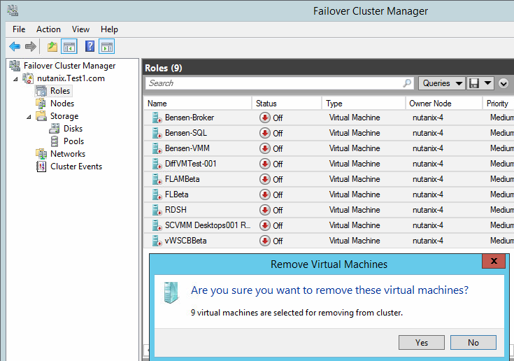
I’ll be transitioning 4 active nodes from a dead and gone domain named test1.com to my active domain dvs.com. First, power off all VMs and remove their association from the old cluster. We’re not touching the storage here so there will be no data loss.
image

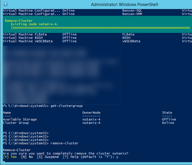
Migration of each node will occur one at a time by first evicting the node to be converted from the old cluster. Important: do this BEFORE you change domains!
image

If, and only if, this is the last and final node you will be migrating, you can now safely destroy the old failover cluster. Do this only on the very last node!
SNAGHTMLf08207b

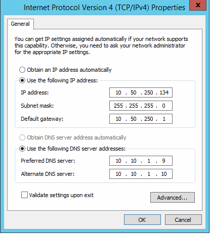
Once a node is ready to make the switch, change the host’s DNS entries to point to the DCs of the domain you will be migrating to, then join the new domain.
image

In with the new

Once your first node is back up, create a new failover cluster. I’m reusing the same IP that was assigned to the old cluster to keep things simple.  Since this is Nutanix which manages its own storage, there are no disks to be managed by the failover cluster, so don’t import anything. Nothing bad will happen if you do, but Hyper-V doesn’t manage these disks so there’s no point. Also, if you run the cluster suitability checks they will fail on the shared storage piece.
image

Repeat this process for each node to be migrated, adding each to the new cluster. Next import your pre-existing VMs into the new cluster and configure them for high availability.
image

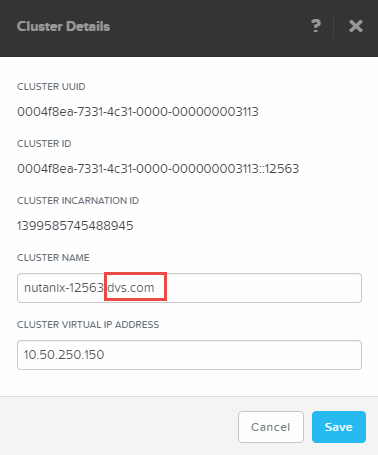
In Prism, just for good measure, update the FQDN in cluster details:
image

Let the Distributed Storage Fabric settle. Once the CVMs are happy, upgrade the NOS if desired.
image

Pretty easy if you do things in the right order. Here is a view of Prism with my 4 hosts converted and only CVMs running. Definitely not a busy cluster at the moment but it is a happy cluster ready for tougher tasks!
image

If things go badly

Maybe you pulled the trigger on the domain switch first before you evicted nodes and destroyed the cluster? If so, any commands directed at the old cluster to the old domain will likely fail with access being denied. You will be prevented from removing the node or destroying the old cluster.
image

If this happens you’ll need to manually remove & restore the cluster services on that node. Since none of the Cmdlets are working it’s time to turn to the registry. Find “ClusDisk” and “ClusSVC” keys within the following path and delete them both. You’ll see entries reflecting the old cluster and old configuration:

HKLM\System\CurrentControlSet\Services\

image

Now you can remove the Failover Clustering feature from the Remove Roles and Features wizard:
image

Reboot the host and install the Failover Clustering feature again. This will set the host back to square one from a clustering perspective, so you can now create a new cluster or join one preexisting.

For more information…

Forcibly removing clustering features
Dell XC Web-scale Appliance Architectures for VDI
Dell XC Web-Scale Converged Appliances
nutanix.com

Server 2012 R2 Hyper-V Core to GUI Conversion

image

There are a number of reasons why this type of conversion might be necessary and if you found this blog post I’m guessing one these applies to you. Maybe you inherited a Server Core environment and are having a hard time managing? Just aren’t a fan of Core and need to convert? Or maybe you installed Core and just want that GUI goodness back. Luckily the GUI can be added to a Core installation via PowerShell without having to reinstall Windows. Trying to upgrade in place using the Install-WindowsFeature cmdlet may fail at 68% after 10 minutes of waiting due to a failure to find the source files (see error below). Of course, nothing is easy so hopefully this will help you get through what was supposed to be a simple conversion if you find yourself in a similar situation.

image

The easiest way to proceed is to first mount the 2012R2 ISO that matches your Core installation and point the cmdlet at the attached source. Of course you can do this via IPMI/ iDRAC or if your ISO files are already on an internal file structure, you can mount and upgrade directly within PowerShell. Very important:  the ISO must match the installed build of your Windows Server Core machine or this process will fail!

First map a drive to your ISO repository, if this goes according to plan it won’t need to be persistent:

image

Next mount the disk image to your server, change the drive letter and ISO name accordingly:


Mount-DiskImage –ImagePath ‘W:\en_windows….ISO’ -Storage Type ISO -PassThru
image

The Mount-DiskImage cmdlet will mount your ISO to the next available drive letter on the host. To determine what that is, pipe your previous command to the Get-Volume cmdlet. You can see that it reveals E as our new drive letter assigned to the mounted ISO:


Mount-DiskImage –ImagePath ‘W:\en_windows….ISO’ -Storage Type ISO -PassThru | Get-Volume

image

If your source ISO has multiple Windows installations within, determine which version is required for your installation by identifying its index so you will install from the proper wim file. In the example below index 4 shows the Server Datacenter product which is what I need. Index 2 show the Standard license level, 1 and 3 show the Core products. This needs to match what you already have installed (Datacenter Core—>Datacenter GUI). If you get an error during the upgrade you’ve either chosen the wrong ISO or the wrong Server build. Volume License vs MSDN, 2012 R2 with Update or without…the distinction matters.


Get-WindowsImage -ImagePath e:\sources\install.wim

image

Run the feature install command and point to the wim file mounted on the new drive letter with the correct Server edition index number (pay close attention to the syntax!). The feature installation will run and if all goes well your server will reboot then come up with the full GUI version of Server in 10-20 minutes.


Install-WindowsFeature Server-GUI-Mgmt-Infra,Server-GUI-Shell -Restart -Source wim:e:\sources\install.wim:4

image

I did this while recovering several hosts from an orphaned AD environment which also orphaned a 4-node failover cluster. Some helpful PowerShell commands useful to me along the way:
Identify Network Interface Index: Get-NetIpConfiguration
DNS Change: Set-DNSClientServerAddress –InterfaceIndex x -ServerAddresses (“10.10.1.10”, “10.10.1.9”)
Domain change: Add-computer -domainname domain.com
Forcibly remove host from a domain: netdom remove ComputerName /domain:DomainName /Force

Resources:

http://mikefrobbins.com/2014/12/25/mount-an-iso-on-a-physical-server-running-server-core/
http://blogs.technet.com/b/john_taylor/archive/2013/01/09/converting-from-server-2012-core-install-to-full-gui.aspx

Hyper-V Server 2012 R2 AVMA

Automatic Virtual Machine Activation (AVMA) is not a new feature but bears repeating as I run across many who forget that it exists or how it works. Simple but powerful, AVMA is a Server 2012 R2 Hyper-V feature that comes at the Datacenter license level and allows an unlimited quantity of seamlessly activated Server VMs on the same host. Very important to distinguish that this does not apply to Windows desktop OSes! Those must be purchased and activated separately using traditional methods. A popular workaround here, useful for other reasons as well, is to deploy Server VMs for use as desktops with the Desktop Experience feature.

Round numbers based on list pricing, if you have 10 or more server VMs to run on a single host, a Datacenter license probably makes good fiscal sense. Considering that a Standard license entitles you to 2 server VMs, below that number it will likely be cheaper to just buy Standard licenses, however you won’t get the AVMA feature.

Implementing AVMA is easy and best done against your template to be cloned either manually or by SCVMM. Once your Hyper-V host is activated, open an elevated command prompt on the Server VM you intend to use as your template and run:

slmgr /ipk

Insert one of the keys below depending on the type of Server VM and features you intend to deploy. These are universal AVMA keys for use in any environment.

Server Edition AVMA key

Datacenter

Y4TGP-NPTV9-HTC2H-7MGQ3-DV4TW

Standard

DBGBW-NPF86-BJVTX-K3WKJ-MTB6V

Essentials

K2XGM-NMBT3-2R6Q8-WF2FK-P36R2

Resources:

Server 2012 R2 AVMA

Hyper-V Design for NUMA Architecture and Alignment

I’m publishing this design topic separately for both Hyper-V and vSphere, assuming that the audience will differ between the two. Some of this content will be repeated between posts but arranged to focus on the hypervisor each prospective reader will likely care most about.
Be sure to also check out: vSphere Design for NUMA Architecture and Alignment (coming soon)
Non-Uniform Memory Access (NUMA) has been with us for awhile now and was created to overcome the scalability limits of the Symmetric Multi-Processing (SMP) CPU architecture. In SMP, all memory access was tied to a singular shared physical bus. There are obvious limitations in this design, especially with higher CPU counts and increased traffic on the bus.
image

NUMA was created to limit the number of CPUs tied to a single memory bus and as a result defines what is construed as a NUMA node. A high performing NUMA node is defined by the memory directly attached to a physical CPU socket accessed directly by consuming applications and services. 
image
NUMA spanning occurs when memory is accessed remote to the NUMA node an application, service or VM is connected to. NUMA spanning means your application or service won’t run out of memory or CPU cores within its NUMA node as it can access the remote DIMMs or cores of an adjacent CPU. The problem with NUMA spanning is that your application or service has to cross the lower performing interconnects to store its pages in the remote DIMMs. This dialog in Hyper-V Settings explains the situation fairly well:
image

What is NUMA alignment?

In the case of virtualization, VMs created on a physical server receive their virtual CPU (vCPU) allotments from the physical CPU cores of their hosts (obviously). There are many tricks used by hypervisors to oversubscribe CPU and run as many VMs on a host as possible while ensuring good performance. Better utilization of physical resources = better return on investment and use of the company dollar. To design your virtual environment to be NUMA aligned means ensuring that your VMs receive vCPUs and RAM tied to a single physical CPU (pCPU), thus ensuring the memory and pCPU cores they access are directly connected and not accessed via traversal of a CPU interconnect (QPI). As fast as interconnects are these days, they are still not as fast as the connection between a DIMM and pCPU.
Running many smaller 1 or 2 vCPU VMs with lower amounts of RAM, such as virtual desktops, aren’t as big of a concern and we generally see very good oversubscription at high performance levels. In the testing my team does at Dell for VDI, we see somewhere between 9-12 vCPUs per pCPU core depending on the workload and VM profile. For larger server-based VMs, such as those used for RDSH sessions, this ratio is smaller and more impactful because there are fewer overall VMs consuming a greater amount of resources. In short, NUMA alignment is much more important when you have VMs with larger vCPU and RAM allocations.
To achieve sustained high performance for a dense server workload, it is important to consider:

  1. The number of  vCPUs assigned to each VM within a NUMA node to avoid contention
  2. The amount RAM assigned to each VM to ensure that all memory access remains within a physical NUMA node.

The following is an example of a balanced configuration based on a dual 12-core, 256GB server used for RDSH. The server hosts 6 high performance VMs that are configured within 2 NUMA node boundaries. Given the number of vCPUs and RAM assigned to each VM, each NUMA node is oversubscribed 2x from a pCPU core perspective and does not exceed the 128GB of RAM available to each pCPU. This ensures that NUMA spanning is not required and minimizes potential contention amongst the VMs. Your oversubscription ratio may vary depending on workload or SLAs.
image

NUMA Alignment in Hyper-V

Let’s walk through a couple of examples in the lab to illustrate this. My Windows cluster consists of:

  • 2 x Dell PowerEdge R610’s with dual X5670 6-core CPUs and 96GB RAM running Server 2012 R2 Datacenter in a Hyper-V Failover Cluster. 24 total logical processors seen by Windows (hyperthreaded).
  • 3 x 2012 R2 VMs named X1, X2, X3 each configured with 12 x vCPUs, 32GB RAM

Looking at the vCPU NUMA configuration of my X2 VM, notice that the hardware defaults to a 2x oversubscription scheme based on the physical server hardware. A NUMA node means 1 pCPU socket so default max vCPUs is 12 in my test server (6-cores hyperthreaded = 12 logical cores). These values can be adjusted on a VM by VM basis and Windows will allow you to assign up to the max logical observed processor count in the server. Here you can see my X2 VM is configured according to a 2x maximum for 12 vCPUs total aligning to the NUMA boundary of a single pCPU. Based on the capability of the pCPUs in my server, the maximum value I can assign to a single VM is 24 vCPUs. Also note that the maximum amount of RAM that can be assigned to a single VM matches that of a single 48GB NUMA node on this server.
image
Hyper-V automatically assigns VMs to NUMA nodes and balances the load between them. Changing this same VM to an allotment of 13 vCPUs, 1 vCPU beyond the configured NUMA boundary, has immediate affects. Now this VM is spanning across 2 NUMA nodes/ pCPU sockets for its vCPU entitlement. CPU contention could occur at this point with other VMs as load increases but memory pages will not become remote unless the memory available to a local NUMA node is exceeded. The same thing happens here if you assign a memory allocation larger than a single NUMA node.
image
To illustrate what is happening here, consider the following drawing. The X3 VM having 13 vCPUs is exceeding the configured maximum of processors for its NUMA topology and must now span 2 physical sockets. Notice that the assigned virtual memory in this configuration is still local to each VM’s primary NUMA node.
image
For a VM to actually be able to store memory pages in a remote NUMA node, the key change that must be made is called out on the main processor tab for the VM spanning NUMA: Dynamic memory must be disabled to allow vNUMA. If dynamic memory is enabled on a VM, no NUMA topology is exposed to the VM, regardless of what settings you change!  Note here also that there is no way to set CPU affinity for a VM in Hyper-V and generally you should never need to. If you want to guarantee a certain percentage of CPU for a VM, set its “Virtual Machine Reserve %” accordingly.
image
NOTE – Remember that if you use Dynamic Memory, you need to carefully consider the values for: Startup, min, max and buffer. What you configure for Startup here is what your VM will boot with and consume as a minimum! If you set your startup to 32GB, your VM will consume 32GB with no workload, reducing what is available to other VMs. Configure your max RAM value as the top end amount you want your VM to expand to.
image
To illustrate the effects of an imbalanced configuration, consider the following PowerShell output. My X2 VM has been assigned 32GB RAM with Dynamic Memory enabled. My X3 VM has also been assigned 32GB RAM but with Dynamic Memory disabled thus forcing NUMA spanning. The “remote physical pages” counters indicate NUMA spanning in action with the X3 VM currently storing 6% of its memory pages in the remote NUMA node. This is with absolutely no workload running mind you.  Lesson: In most cases, you want to leave Dynamic Memory enabled to achieve the best performance and balance of resources! Commands used below:

Get-VM
Get-VMProcessor
Get-counter “\hyper-v VM VID Partition(*)\*”

image
Here is a visual of what’s happening with X3 spanning NUMA. A percentage of its memory pages are being stored in the remote NUMA node 0 which requires crossing the QPI links to access, thus reducing performance:
image
Look what happens when I re-enable Dynamic Memory on X3. You want to always see the values for “remote physical pages” as 0:
image
The risk of this happening is greater with VMs with heavy resource requirements. There may be some instances where the performance tradeoff is worth it, simply because you have a VM that absolutely requires more resources. Look at what happens when I bring my X1 VM online configured with 64GB static RAM on the same server:
image
It is immediately punted to the second server in my cluster that has enough resources to power it on. If the cluster had too few resources available on any node, the VM would fail to power on.
image
It’s worth noting that if you have your VMs set to save state when the Hyper-V host shuts down, be prepared to consume a potentially enormous amount of disk. When this is enabled Hyper-V will write a BIN file equal to the amount of RAM in use by the VM. If you disabled Dynamic Memory then the BIN file will be the full amount of assigned RAM.
image
32GB on disk for my X3 VM with Dynamic Memory disabled:
image

Key Takeaways

  • Designing your virtual infrastructure to work in concert with the physical NUMA boundaries of your servers will net optimal performance and minimize contention, especially for VMs with large resource assignments.
  • A single VM consuming more vCPUs than a single NUMA node contains, will be scheduled across multiple physical NUMA nodes causing possible CPU contention as loads increase.
  • A single or multiple VMs consuming more RAM than a single NUMA node contains will span NUMA and store a percentage of their memory pages in the the remote NUMA node causing reduced performance.
  • In Hyper-V, in most cases, you want to leave Dynamic Memory enabled so the server can adjust using a balloon driver as required.
  • CPU affinity does not exist in Hyper-V. If you want to assign a VM a guaranteed slice of CPU, set its “virtual machine reserve %” in its CPU settings.
  • Virtual memory assignments are cumulative, more impactful when not using dynamic memory.
  • Virtual CPU assignments are non-cumulative and will not force a VM to span NUMA as long as a vCPU assignment falls within the limits of a defined NUMA node. A vCPU assignment that exceeds the boundaries of a configured NUMA node will cause spanning.
  • Be careful what you set your “automatic stop action” to in Hyper-V manager or SCVMM. If set to save state, large BIN files will be written to disk equaling the memory in use by each VM.

Resources:

http://lse.sourceforge.net/numa/faq/
Hyper-V Virtual NUMA Overview
Hyper-V 2012 Checklist

Dell XC Series 2.0: Product Architectures

Following our launch of the new 13G-based XC series platform, I present our product architectures for the VDI-specific use cases. Of the platforms available, this use case is focused on the extremely powerful 1U XC630 with Haswell CPUs and 2133MHz RAM. We offer these appliances on both Server 2012 R2 Hyper-V and vSphere 5.5 U2 with Citrix XenDesktop, VMware Horizon View, or Dell vWorkspace.  All platform architectures have been optimized, configured for best performance and documented.
dn

Platforms

We have three platforms to choose from optimized around cost and performance, all being ultimately flexible should specific parameters need to change. The A5 model is the most cost effective leveraging 8-core CPUs, 256GB RAM 2 x 200GB SSDs for performance and 4 x 1TB HDDs for capacity.  For POCs, small deployments or light application virtualization, this platform is well suited. The B5 model steps up the performance by adding four cores per socket, increasing the RAM density to 384GB and doubling the performance tier to 2 x 400GB SSDs. This platform will provide the best bang for the buck on medium density deployments of light or medium level workloads. The B7 is the top of the line offering 16-core CPUs and a higher capacity tier of 6 x 1TB HDDs. For deployments requiring maximum density of knowledge or power user workloads, this is the platform for you.
image
At 1U with dual CPUs, 24 DIMM slots and 10 drive bays…loads of potential and flexibility!
image

Solution Architecture

Utilizing 3 platform hardware configurations, we are offering 3 VDI solutions on 2 hypervisors. Lots of flexibility and many options. 3 node cluster minimum is required with every node containing a Nutanix Controller VM (CVM) to handle all IO. The SATADOM is present for boot responsibilities to host the hypervisor as well as initial setup of the Nutanix Home area. The SSDs and NL SAS disks are passed through directly to each CVM which straddle the hypervisor and hardware. Every CVM contributes its directly-attached disks to the storage pool which is stretched across all nodes in the Nutanix Distributed File System (NDFS) cluster. NDFS is not dependent on the hypervisor for HA or clustering. Hyper-V cluster storage pools will present SMB version 3 to the hosts and vSphere clusters will be presented with NFS. Containers can be created within the storage pool to logically separate VMs based on function. These containers also provide isolation of configurable storage characteristics in the form of dedupe and compression. In other words, you can enable compression on your management VMs within their dedicated container, but not on your VDI desktops, also within their own container. The namespace is presented to the cluster in the form of \\NDFS_Cluster_name\container_name.
The first solution I’ll cover is Dell’s Wyse vWorkspace which supports either 2012 R2 Hyper-V or vSphere 5.5. For small deployments or POCs we offer this solution in a “floating mgmt” architecture which combines the vWorkspace infrastructure management roles and VDI desktops or shared session VMs. vWorkspace and Hyper-V enables a special technology for non-persistent/ shared image desktops called Hyper-V Catalyst which includes 2 components: HyperCache and HyperDeploy. Hyper-V Catalyst provides some incredible performance boosts and requires that the vWorkspace infrastructure components communicate directly with the hyper-V hypervisor. This also means that vWorkspace does not require SCVMM to perform provisioning tasks for non-persistent desktops!

  • HyperCache – Provides virtual desktop performance enhancement by caching parent VHDs in host RAM. Read requests are satisfied from cache including requests from all subsequent child VMs.
  • HyperDeploy – Provides instant cloning of parent VHDs massively diminishing virtual desktop pool deployment times.

You’ll notice the HyperCache components included on the Hyper-V architectures below. 3 to 6 hosts in the floating management model, depicted below with management, desktops and RDSH VMs logically separated only from a storage container perspective by function. The recommendation of 3-7 RDSH VMs is based our work optimizing around NUMA boundaries. I’ll dive deeper into that in an upcoming post. The B7 platform is used in the architectures below.
image
Above ~1000 users we recommend the traditional distributed management architecture to enable more predictable scaling and performance of both the compute and management hosts. The same basic architecture is the same and scales to the full extent supported by the hypervisor, is this case Hyper-V which supports up to 64 hosts. NDFS does not have a scaling limitation so several hypervisor clusters can be built within a single contiguous NDFS namespace. Our recommendation is to then build independent Failover Clusters for compute and management discretely so they can scale up or out independently.
The architecture below depicts a B7 build on Hyper-V applicable to Citrix XenDesktop or Wyse vWorkspace.
image

This architecture is relatively similar for Wyse vWorkspace or VMware Horizon View on vSphere 5.5 U2 but fewer total compute hosts per HA cluster, 32 total. For vWorkspace, Hyper-V Catalyst is not present in this scenario so vCenter is required to perform desktop provisioning tasks.
image
For the storage containers, the best practice of less is more still stands. If you don’t need a particular feature don’t enable it, as it will consume additional resources. Deduplication is always recommended on the performance tier since the primary OpLog lives on SSD and will always benefit. Dedupe or compression on the capacity tier is not recommended, of course you absolutely need it. And if you do prepare to increase each CVM RAM allocation to 32GB.

Container Purpose Replication Factor Perf Tier Deduplication Capacity Tier Deduplication Compression
Ds_compute Desktop VMs 2 Enabled Disabled Disabled
Ds_mgmt Mgmt Infra VMs 2 Enabled Disabled Disabled
Ds_rdsh RDSH Server VMs 2 Enabled Disabled Disabled

Network Architecture

As a hyperconverged appliance, the network architecture leverages the converged model. A pair of 10Gb NICs minimum in  each node handle all traffic for the hypervisor, guests and storage operations between CVMs. Remember that the storage of all VMs is kept local to the host to which the VM resides, so the only traffic that will traverse the network is LAN and replication. There is no need to isolate storage protocol traffic when using Nutanix. 
Hyper-V and vSphere are functionally similar. For Hyper-V there are 2 vSwitches per host, 1 external that aggregates all of the services of the host management OS as well as the vNICs for the connected VMs. The 10Gb NICs are connected to a LBFO team configured in Dynamic Mode. The CVM alone connects to a private internal vSwitch so it can communicate with the hypervisor.
image
In vSphere it’s the same story but with the concept of Port Groups and vMotion.
image
We have tested the various configurations per our standard processes and documented the performance results which can be found in the link below. These docs will be updated as we validate additional configurations.

Product Architectures for 13G XC launch:

Resources:

About Wyse vWorkspace HyperCache
About Wyse vWorkspace HyperDeploy
SJbWUYl4LRCwFNcatHuG

Dell XC Series Web-scale Converged Appliance 2.0

I am pleased to present the Dell XC 2.0 series of web-scale appliances based on the award-winning 13G PowerEdge server line from Dell. There’s lots more in store for the XC so just focusing on this part of the launch we are introducing the XC630 and the XC730xd appliances.

Flexibility and performance are key tenets of this launch providing not only a choice in 1U or 2U form factors, but an assortment of CPU and disk options. From a solution perspective, specifically around VDI, we are releasing three optimized and validated platforms with accompanied Product Architectures to help you plan and size your Dell XC deployments.

The basic architecture of the Dell XC powered by Nutanix remains the same. Every node is outfitted with a Nutanix Controller VM (CVM) that connects to a mix of SSD and HDD to contribute to a distributed storage pool that has no inherent scaling limitation. Three nodes minimum required and either VMware vSphere or Microsoft Windows Server 2012 R2 Hyper-V are supported hypervisors. Let’s take a look at the new models.

image

XC630

The XC630 is a 1U dual-socket platform that supports 6-core to 16-core CPUs and up to 24 x 2133MHz 16GB RDIMMs or 32GB LRDIMMs. The XC630 can be configured using all flash or using two tiers of storage which can consist of 2 to 4 x SSDs (200GB, 400GB or 800GB) and 4 to 8 x 1TB HDDs (2TB HDDs coming soon). Flexible! All flash nodes must have a minimum of 6 x SSDs while nodes with two storage tiers must have a minimum of two SSDs and four HDDs. All nodes have a minimum of 2 x 1Gb plus 2 x 10Gb SFP+ or BaseT Ethernet that can be augmented via an additional card.

New to the XC 2.0 series is a 64GB SATADOM that is used to boot each node. Each node is also outfitted with a 16GB SD card used for the purposes of initial deployment and recovery. The SSDs and HDDs that comprise the Nutanix Distributed File System (NDFS) storage pool are presented to each CVM via an on-board 1GB PERC H730 set in pass-through mode. Simple, powerful, flexible.

image


XC730xd

For deployments requiring a greater amount of cold tier data capacity, the XC730xd can provide up to 32TB raw per node. The XC730xd is a 2U dual-socket platform that supports 6-core to 16-core CPUs and up to 24 x 2133MHz 16GB RDIMMs or 32GB LRDIMMs. The XC730xd is provided with two chassis options: 24 x 2.5” disks or 12 x 3.5” disks. The 24-drive model requires the use of two tiers of storage which can consist of 2 to 4 x SSDs (200GB, 400GB or 800GB) and 4 to 22 x 1TB HDDs .The 12-drive model also requires two tiers of storage consisting of 2 to 4 x SSDs (200, 400GB or 800GB) and up to 10 x 4TB HDDs. All nodes have a minimum of 2 x 1Gb plus 2 x 10Gb SFP+ or BaseT Ethernet that can be augmented via an additional card.

The XC730xd platforms are also outfitted with a 64GB SATADOM that is used to boot the nodes. The 16GB SD card used for the purposes of initial deployment and recovery is present on these models as well. The SSDs and HDDs that comprise the Nutanix Distributed File System (NDFS) storage pool are presented to each CVM via an on-board 1GB PERC H730 set in pass-through mode. Simple, powerful, flexible.

12 drive option, hopefully the overlaps in the image below make sense:

image


24 drive option:

image


Nutanix Software Editions

All editions of the Nutanix software platform are available with variable lengths for support and maintenance.

image

This is just the beginning. Keep an eye out for additional platforms and offerings from the Dell + Nutanix partnership! Next up is the VDI product architectures based on the XC630. Stay tuned!!

http://www.dell.com/us/business/p/dell-xc-series/pd

Proper Shut Down of Nutanix 2012 R2 Hyper-V Cluster

Happy 2015!! I’m seriously backed up and delinquent on blog posts so prepare for a deluge of interesting topics soon.

image

As painful and hopefully unlikely as this scenario may be, better to have a planned and controlled outage vs unplanned with potential data loss, or worse. This post covers the cluster shutdown process for Nutanix with Hyper-V. In case you didn’t know, Nutanix is not dependent on Windows or vSphere for clustering, as it handles its own HA mechanism. This does require, however, that you consider the independent Nutanix cluster services to ensure a graceful shutdown.

In the references at the bottom, you’ll notice that for vSphere clusters, the method described there is to shut down the Nutanix cluster first, then the vSphere cluster. For Hyper-V the procedure is reversed, requiring that the Hyper-V cluster be shut down first, then the Nutanix cluster. If you shut down your Nutanix cluster services first, you won’t be able to connect to your Failover Cluster to properly shut it down.

Shut Down Failover Cluster

  1. Gracefully shut down all VMs (Not Nutanix CVMs, yet!!)
  2. Open Failover Cluster Manager (cluadmin.msc) and connect to the Failover Cluster
  3. Right-click the cluster name, select “more actions” –> “shut down cluster”, select “yes” to confirm
    • Alternatively, in PowerShell enter: “Stop-Cluster”

Once the Hyper-V cluster is shut down, you can begin to shut down the Nutanix cluster.

Shut Down Nutanix Cluster

  1. SSH or connect to any CVM console, log in
  2. Enter “cluster stop” (root not required)
  3. Once completed successfully, you will see confirmation that all services have stopped on all CVMs:
  4. Shut down each CVM on all hosts:
  5. Lastly, shut down each physical Hyper-V node – This can be done of number of ways, onesy twosy, PowerShell, or via the Remote Shutdown UI (shutdown /i) for bulk operation:

Startup is the reverse, ensuring that your Nutanix cluster is up and running properly before starting your failover cluster.

References:

http://blogs.msdn.com/b/clustering/archive/2013/08/23/10443912.aspx

http://port5480.blogspot.com/2014/10/shut-down-nutanix-cluster.html

Clustering Server 2012 R2 with iSCSI Storage

Yay, last post of 2014! Haven’t invested in the hyperconverged Software Defined Storage model yet? No problem, there’s still time. In the meanwhile, here is how to cluster Server 2012 R2 using tried and true EqualLogic iSCSI shared storage.

EQL Group Manager

First, prepare your storage array(s), by logging into EQL Group Manager. This post assumes that your basic array IP, access and security settings are in place.  Set up your local CHAP account to be used later. Your organization’s security access policies or requirements might dictate a different standard here.

SNAGHTML3b62e029

Create and assign an Access Policy to the VDS/VSS in Group Manager otherwise this volume will not be accessible. This will make subsequent steps easier when it’s time to configure ASM.image

Create some volumes in Group Manager now so you can connect your initiators easily in the next step. It’s a good idea to create your cluster quorum LUN now as well.

image


Host Network Configuration

First configure the interfaces you intend to use for iSCSI on your cluster nodes. Best practice says that you should limit your iSCSI traffic to a private Layer2 segment, not routed and only connecting to the devices that will participate in the fabric. This is no different from Fiber Channel in that regard, unless you are using a converged methodology and sharing your higher bandwidth NICs. If using Broadcom NICs you can choose Jumbo Frames or hardware offload, the larger frames will likely net a greater performance impact. Each host NIC used to access your storage targets should have a unique IP address able to access the network of those targets within the same private Layer2 segment. While these NICs can technically be teamed using the native Windows LBFO mechanism, best practice says that you shouldn’t, especially if you plan to use MPIO to load balance traffic. If your NICs will be shared (not dedicated to iSCSI alone) then LBFO teaming is supported in that configuration. To keep things clean and simple I’ll be using 4 NICs, 2 dedicated to LAN, 2 dedicated to iSCSI SAN. Both LAN and SAN connections are physically separated to their own switching fabrics as well, this is also a best practice.

image

MPIO – the manual method

First, start the MS iSCSI service, which you will be prompted to do, and check its status in PowerShell using get-service –name msiscsi.

image

Next, install MPIO using Install-WindowsFeature Multipath-IO

Once installed and your server has been rebooted, you can set additional options in PowerShell or via the MPIO dialog under  File and Storage Services—> Tools.

image

Open the MPIO settings and tick “add support for iSCSI devices” under Discover Multi-Paths. Reboot again. Any change you make here will ask you to reboot. Make all changes once so you only have to do this one time.

image

The easier way to do this from the onset is using the EqualLogic Host Integration Tools (HIT Kit) on your hosts. If you don’t want to use HIT for some reason, you can skip from here down to the “Connect to iSCSI Storage” section.

Install EQL HIT Kit (The Easier Method)

The EqualLogic HIT Kit will make it much easier to connect to your storage array as well as configure the MPIO DSM for the EQL arrays. Better integration, easier to optimize performance, better analytics. If there is a HIT Kit available for your chosen OS, you should absolutely install and use it. Fortunately there is indeed a HIT Kit available for Server 2012 R2.

image

Configure MPIO and PS group access via the links in the resulting dialog.

image

In ASM (launched via the “configure…” links above), add the PS group and configure its access. Connect to the VSS volume using the CHAP account and password specified previously. If the VDS/VSS volume is not accessible on your EQL array, this step will fail!

image

Connect to iSCSI targets

Once your server is back up from the last reboot, launch the iSCSI Initiator tool and you should see any discovered targets, assuming they are configured and online. If you used the HIT Kit you will already be connected to the VSS control volume and will see the Dell EQL MPIO tab.

image

Choose an inactive target in the discovered targets list and click connect, be sure to enable multi-path in the pop-up that follows, then click Advanced.

image

Enable CHAP log on, specify the user/pw set up previously:

image

If your configuration is good the status of your target will change to Connected immediately. Once your targets are connected, the raw disks will be visible in Disk Manager and can be brought online by Windows.

image

When you create new volumes on these disks, save yourself some pain down the road and give them the same label as what you assigned in Group Manager! The following information can be pulled out of the ASM tool for each volume:

image

Failover Clustering

With all the storage pre-requisites in place you can now build your cluster. Setting up a Failover Cluster has never been easier, assuming all your ducks are in a row. Create your new cluster using the Failover Cluster Manager tool and let it run all compatibility checks.

image

Make sure your patches and software levels are identical between cluster nodes or you’ll likely fail the clustering pre-check with differing DSM versions:

image

Once the cluster is built, you can manipulate your cluster disks and bring any online as required. Cluster disks will not be able to be brought online until all nodes in the cluster can access the disk.

image

Next add your cluster disks to Cluster Shared Volumes to enable multi-host read/write and HA.

image

The new status will be reflected once this change is made.

image

Configure your Quorum to use the disk witness volume you created earlier. This disk does not need to be a CSV.

image

Check your cluster networks and make sure that iSCSI is set to not allow cluster network communication. Make sure that your cluster network is setup to allow cluster network communication as well as allowing client connections. This can of course be further segregated if desired using additional NICs to separate cluster and client communication.

image

Now your cluster is complete and you can begin adding HA VMs, if using Hyper-V, SQL, File or other roles as required.

References:

http://blogs.technet.com/b/keithmayer/archive/2013/03/12/speaking-iscsi-with-windows-server-2012-and-hyper-v.aspx

http://blogs.technet.com/b/askpfeplat/archive/2013/03/18/is-nic-teaming-in-windows-server-2012-supported-for-iscsi-or-not-supported-for-iscsi-that-is-the-question.aspx

Dell XC Series – Product Architectures

Hyperconverged Web-scale Software Defined Storage (SDS) solutions are white hot right now and Nutanix is leading the pack with their ability to support all major hypervisors (vSphere, Hyper-V and KVM) while providing nearly unlimited scale. Dell partnering with Nutanix was an obvious mutually beneficial choice for the reasons above plus supplying a much more robust server platform. Dell also provides a global reach for services and support as well as solving other challenges such as hypervisors installed in the factory.

Nutanix operates below the hypervisor layer so as a result requires a lot of tightly coupled interaction with the hardware directly. Many competing platforms in this space sit above the hypervisor so require vSphere, for example, to provide access to storage and HA but they are also limited by the hypervisor’s limitations (scale).  Nutanix uses its own algorithm for clustering and doesn’t rely on a common transactional database which can cause additional challenges when building solutions that span multiple sites. Because of this the Nutanix Distributed Filesystem (NDFS) supports no known limits of scale. There are current Nutanix installations in the thousands of nodes across a contiguous namespace and now you can build them on Dell hardware.

Along with the Dell XC720xd appliances, we have released a number of complementary workload Product Architectures to help customers and partners build solutions using these new platforms. I’ll discuss the primary architectural elements below.

Wyse Datacenter Appliance Architecture for Citrix

Wyse Datacenter Appliance Architecture for VMware

Wyse Datacenter Appliance Architecture for vWorkspace


Nutanix Architecture

Three nodes minimum are required for NDFS to achieve quorum so that is the minimum solution buy in, then storage and compute capacity can be increased incrementally beyond by adding one or more nodes to an existing cluster. The Nutanix architecture uses a Controller VM (CVM) on each host which participates in the NDFS cluster and manages the hard disks local to its own host. Each host requires two tiers of storage: high performance/ SSD and capacity/ HDD. The CVM manages the reads/writes on each host and automatically tiers the IO across these disks. A key value proposition of the Nutanix model is data locality which means that the data for a given VM running on a given host is stored locally on that host as apposed to having reads and writes crossing the network. This model scales indefinitely in a linear block manner where you simply buy and add capacity as you need it. Nutanix creates a storage pool that is distributed across all hosts in the cluster and presents this pool back to the hypervisor as NFS or SMB.

You can see from the figure below that the CVM engages directly with the SCSI controller through which it accesses the disks local to the host it resides. Since Nutanix sits below the hypervisor and handles its own clustering and data HA, it is not dependent upon the hypervisor to provide any features nor is it limited by any related limitations.

image

From a storage management and feature perspective, Nutanix provides two tiers of optional deduplication performed locally on each host (SSD and HDD individually), compression, tunable replication (number of copies of each write spread across disparate nodes in the cluster) and data locality (keeps data local to the node the VM lives on). Within a storage pool, containers are created to logically group VMs stored within the namespace and enable specific storage features such as replication factor and dedupe. Best practice says that a single storage pool spread across all disks is sufficient but multiple containers can be used. The image below shows an example large scale XC-based cluster with a single storage pool and multiple containers.

image

While the Nutanix architecture can theoretically scale indefinitely, practicality might dictate that you design your clusters around the boundaries of the hypervisors, 32 nodes for vSphere, 64 nodes for Hyper-v. The decision to do this will be more financially impactful if you separate your resources along the lines of compute and management in distinct SDS clusters. You could also, optionally, install many maximum node hypervisor clusters within a single very large, contiguous Nutanix namespace, which is fully supported. I’ll discuss the former option below as part of our recommended pod architecture.

Dell XC720xd platforms

For our phase 1 launch we have five platforms to offer that vary in CPU, RAM and size/ quantity of disks. Each appliance is 2U, based on the 3.5” 12-gen PowerEdge R720XD and supports from 5 to 12 total disks, each a mix of SSD and HDD. The A5 platform is the smallest with a pair of 6-core CPUs, 200GB SSDs and a recommended 256GB RAM. The B5 and B7 models are almost identical except for the 8-core CPU on the B5 and the 10-core CPU on the B7. The C5 and C7 boast a slightly higher clocked 10-core CPU with doubled SSD densities and 4-5x more in the capacity tier. The suggested workloads are specific with the first three targeted at VDI customers. If greater capacity is required, the C5 and C7 models work very well for this purpose too.

image

For workload to platform sizing guidance, we make the following recommendations:

Platform

Workload

Special Considerations

A5

Basic/ light task users, app virt

Be mindful of limited CPU cores and RAM densities

B5

Medium knowledge workers

Additional 4 cores and greater RAM to host more VMs or sessions

B7

Heavy power users

20 cores per node + a recommended 512GB RAM to minimize

oversubscription

C5 Heavy power users Higher density SSDs + 20TB in the capacity tier for large VMs or amount of user data
C7 Heavy power users Increased number of SSDs with larger capacity for greater amount of T1 performance

Here is a view of the 12G-based platform representing the A5-B7 models. The C5 and C7 would add additional disks in the second disk bay. The two disks in the rear flexbay are 160GB SSDs configured in RAID1 via PERC used to host the hypervisor and CVM, these disks do not participate in the storage pool. The six disks in front are controlled by the CVM directly via the LSI controller and contribute to the distributed storage pool across all nodes.

image

Dell XC Pod Architecture

This being a 10Gb hyperconverged architecture, the leaf/ spine network model is recommended. We do recommend a 1Gb switch stack for iDRAC/ IPMI traffic and build the leaf layer from 10Gb Force10 parts. The S4810 is shown in the graphic below which is recommended for SFP+ based platforms or the S4820T can be used for 10GBase-T.

image

In our XC series product architecture, the compute, management and storage layers, typically all separated, are combined here into a single appliance. For solutions based on vWorkspace under 10 nodes, we recommend a “floating management” architecture which allows the server infrastructure VMs to move between hosts also being used for desktop VMs or RDSH sessions. You’ll notice in the graphics below that compute and management are combined into a single hypervisor cluster which hosts both of these functions.

Hyper-V is shown below which means the CVMs present the SMBv3 protocol to the storage pool. We recommend three basic containers to separate infrastructure mgmt, desktop VMs and RDSH VMs. We recommend the following feature attributes based on these three containers (It is not supported to enable compression and deduplication on the same container):

Container

Purpose

Replication Factor

Perf Tier Deduplication

Capacity Tier Deduplication

Compression

Ds_compute

Desktop VMs

2

Enabled

Enabled

Disabled

Ds_mgmt

Mgmt Infra VMs

2

Enabled

Disabled

Disabled

Ds_rdsh

RDSH Server VMs

2

Enabled

Enabled

Disabled

You’ll notice that I’ve included the resource requirements for the Nutanix CVMs (8 x vCPUs, 32GB vRAM). The vRAM allocation can vary depending on the features you enable within your SDS cluster. 32GB is required, for example, if you intend to enable both SSD and HDD deduplication. If you only require SSD deduplication and leave the HDD tier turned off, you can reduce your CVM vRAM allocation to 16GB. We highly recommend that you disable any features that you do not need or do not intend to use!

image

For vWorkspace solutions over 1000 users or solutions based on VMware Horizon or Citrix XenDesktop, we recommend separating the infrastructure management in all cases. This allows management infrastructure to run in its own dedicated hypervisor cluster while providing very clear and predictable compute capacity for the compute cluster. The graphic below depicts a 1000-6000 user architecture based on vWorkspace on Hyper-V. Notice that the SMB namespace is stretched across both of the discrete compute and management infrastructure clusters, each scaling independently. You could optionally build dedicated SDS clusters for compute and management if you desire, but remember the three node minimum, which would raise your minimum build to 6 nodes in this scenario.

image

XenDesktop on vSphere, up to 32 nodes max per cluster, supporting around 2500 users in this architecture:

image

Horizon View on vSphere, up to 32 nodes max per cluster. supporting around 1700 users in this architecture:

image

Network Architecture

Following the leaf/ spine model, each node should connect 2 x 10Gb ports to a leaf switch which are then fully mesh connected to an upstream set of spine switches.

image

On each host there are two virtual switches: one for external access to the LAN and internode communication and one private internal vSwitch used for the CVM alone. On Hyper-V the two NICs are configured in a LBFO team on each host with all management OS vNICs connected to it.

image

vSphere follows the same basic model except for port groups configured for the VM type and VMKernel ports configured for host functions:

image

Performance results

The tables below summarize the user densities observed for each platform during our testing. Please refer to the product architectures linked at the beginning of this post for the detailed performance results for each solution.

image

image

Resources:

http://en.community.dell.com/dell-blogs/direct2dell/b/direct2dell/archive/2014/11/05/dell-world-two-questions-cloud-client-computing

http://blogs.citrix.com/2014/11/07/dell-launches-new-appliance-solution-for-desktop-virtualization/

http://blogs.citrix.com/2014/11/10/xendesktop-technologies-introduced-as-a-new-dell-wyse-datacenter-appliance-architecture/

http://blogs.vmware.com/euc/2014/11/vmware-horizon-6-dell-xc-delivering-new-economics-simplicity-desktop-application-virtualization.html

http://stevenpoitras.com/the-nutanix-bible/

http://www.dell.com/us/business/p/dell-xc-series/pd

Fun with Storage Spaces in Windows Server 2012 R2

image

Previously I took at look at a small three disk Storage Spaces configuration on Windows 8.1 for my Plex media server build. Looking at the performance of the individual disks, I grew curious so set out to explore Spaces performance in Server 2012 R2 with one extra disk. Windows 8.1 and Server 2012 R2 are cut from the same cloth with the Server product adding performance tiering, deduplication and means for larger scale.  At its core, Storage Spaces is essentially the same between the products and accomplishes a singular goal: take several raw disks and create a pool with adjustable performance and resiliency characteristics. The execution of this however, is very different between the products.

For my test bed I used a single Dell PowerEdge R610 which has 6 local 15K SAS disks attached to a PERC H700 RAID controller with 1GB battery-backed cache. Two disks in RAID 1 for the OS (Windows Server 2012 R2) and four disks left for Spaces. Spaces is a very capable storage aggregation tool that can be used with large external JBODs and clustered across physical server nodes, but for this exercise I want to look only at local disks and compare performance between three and four disk configurations.

Questions I’m looking to answer:

  • Do 2 columns outperform 1? (To learn about columns in Spaces, read this great article)
  • Do 4-disk Spaces greatly outperform 3-disk Spaces?
  • What advantage, if any, does controller cache bring to the table?
  • Are there any other advantages in Spaces for Server 2012 R2 that outperform the Windows 8.1 variant (aside from SSD tiering, dedupe and scale)?

No RAID

The first rule of Storage Spaces is: thou shalt have no RAID in between the disks and the Windows OS. Spaces handles the striping and resiliency manipulation itself so can’t have hardware or software RAID in the way. The simplest way to accomplish this is via the use of a pass-through SAS HBA but if you only have RAID controller at your disposal, it can work by setting all disks to RAID 0. For Dell servers, in the OpenManage Server Administrator (OMSA) console, create a new Virtual Disk for every physical disk you want to include, and set its layout to RAID-0. *NOTE – There are two uses of the term “virtual disk” in this scenario. Virtual Disk in the Dell storage sense is not to be confused with virtual disk in the Windows sense, although both are ultimately used to create a logical disk from a physical resource.

image

To test the native capability of Spaces with no PERC hardware cache assist, I set the following policy on each Virtual Disk:

image

Make some Spaces!

Windows will now see these local drives as assignable disks to a Storage Pool. From the File and Storage Services tab in Server Manager, launch the New Storage Pool Wizard. This is where creating Spaces in Windows 8.1 and Server 2012 R2 divest in a major way. What took just a few clicks on a single management pane in Win8.1 takes several screens and multiple wizards in Server 2012 R2. Also, all of this can be done in PowerShell using the new-storagepool and new-virtualdisk cmdlets. First name the new storage pool:

image

Add physical disks to the pool, confirm and commit.

image

You will now see your new pool created under the Storage Spaces section. Next create new virtual disks within the pool by right-clicking and selecting “New Virtual Disk”.

image

Select the pool to create the Virtual Disk within and name it. You’ll notice that this is where you would enable performance tiering if you had the proper disks in place using at least one SDD and one HDD.

image

Choose the Storage Layout (called resiliency in Win8.1 and in PowerShell). I previously determined that Mirror Spaces are the best way to go so will be sticking with that layout for these investigations.

image

Choices are good, but we want to save committed capacity, choose Thin Provisioning:

image

Specify the size:

image

Confirm and commit:

image

Now we have a pool (Storage Space) and a Virtual Disk, now we need to create a volume. Honestly I don’t know why Microsoft didn’t combine this next step with the previous Virtual Disk creation dialogs, as a Virtual Disk with no file system or drive letter is utterly useless.

image

Next select the size of the volume you want to create (smaller than or equal to the vDisk size specified previously), assign a drive letter and file system. It is recommended to use ReFS whenever possible. Confirm and commit.

image

Finally, a usable Storage Space presented to the OS as a drive letter!

Performance Baseline

First, to set a baseline I created a 4-disk RAID10 set using the integrated PERC H700 with 1GB cache (enabled). I copied a 6GB file back and forth between the C:\ and M:\ drives to test 100% read and 100% write operations. Write IO was fairly poor not even breaking 20 IOPS, the RAID10 double write penalty in full effect. Reads were much better, as expected, nearing 300 IOPS at peak.

image

3-Disk Mirror Space Performance

To force the server to go to disk for all IO operations (since I simply moved the same 6GB file between volumes), I used a little utility called Flush Windows Cache File by DelphiTools. This very simple CLI tool flushes the file cache and memory working sets along with the modified and purged memory standby lists.

Test constants: 3-disk Mirror space, PERC caching disabled, single column (default for 3 disks), 6GB file used to simulate a 100% read operation and a 100% write operation:image

image

Here are a few write operations followed by a read operation to demonstrate the disk performance capabilities. Write IOPS spike ~30 with read IOPS ~170. Interestingly, the write performance is better than RAID10 on the PERC here with read performance at almost half.

image

Turning the PERC caching back on doesn’t help performance at all, for reads or writes.

image

4-Disk Space, 1 Column Performance

Test constants: 4-disk Mirror space, PERC caching enabled, single column, 6GB file used to simulate a 100% read operation and a 100% write operation:

When adding a 4th disk to a 3-disk Space, the column layout has already been determined to be singular, so this does not change. To use a two column layout with four disks, the space would need to be destroyed and recreated. Let’s see how four disks perform with one column.

image

You’ll notice in the vDisk output that the Allocated size is larger now with the 4th disk, but the number of columns is unchanged at 1.

image

Adding the 4th disk to the existing 3-disk Space doesn’t appear to have helped performance at all. Even with PERC caching enabled, there is no discernable difference in performance between 3 disks or 4 using a single column, so the extra spindle adds nothing here. Disabling PERC cache appears to make no difference so I’ll skip that test here.

image

4-Disk Space, 2 Column Performance

Test constants: 4-disk Mirror space, PERC caching enabled, two columns, 6GB file used to simulate a 100% read operation and a 100% write operation.

Using 4 disks by default will create Virtual Disks with 2 columns as confirmed in PowerShell, this is also the minimum number of disks required to use two columns:

image

WOW! Huge performance difference with four disks and two columns. The read performance is consistently high (over 700 IOPS) with the writes performing in a wider arc upwards of 300 IOPS. This is a 1000% performance increase for writes and 300% increase for reads. Literally off the chart! Spaces is allowing each of these participating disks to exhibit their full performance potential individually.

image

Thinking this is too good to be true, I disabled the PERC cache and ran the test again. This is no fluke, I got very close to the same results the second time with all disks participating. Incredible.

image

Plex Performance

Since I began this whole adventure with Plex in mind, fitting that I should end it there too. Streaming a compatible file across the network yielded the following results. Skipping around in the file, all four disks were read from at some point during the stream, half spiking ~110 IOPS, the other two ~80 IOPS. This is twice the amount of observed performance on my home 3-disk 7.2k SATA-based HTPC.

image

Conclusions:

Using 15K SAS disks here, which are theoretically capable of ~200 IOPS each, performance is very good overall and seems to mitigate much of the overhead typically seen in a traditional RAID configuration. Spaces provides the resilient protection of a RAID configuration while allowing each disk in the set to maximize its own performance characteristics. The 3-disk one column Spaces configuration works but is very low performing. Four disks with one column don’t perform any better, so there is significant value in running a configuration that supports two or more columns. Columns are what drive the performance differential and the cool thing about Spaces is that they are tunable. Four disks with a two column configuration should be your minimum consideration for Spaces, as the performance increase adding that second column is substantial. Starting with three disks and adding a fourth will persist your single column configuration so is not advised. Best to just start with at least four disks. PERC caching showed to neither add nor detract from performance when used in conjunction with Spaces, so you could essentially ignore it altogether. Save your money and invest in SAS pass-through modules instead. The common theme that sticks out here is that the number of columns absolutely matters when it comes to performance in Spaces. The column-to-disk correlation ratio for a two-way mirror is 1:2, so you have to have a minimum of four disks to use two columns. Three disks and one column work fine for Plex but if you can start with four, do that.

Resources:

Storage Spaces FAQs

Storage Spaces – Designing for Performance

This post originated at Exit.the.Fast.Lane | Weestro.blogspot.com