Deploying VMware VSAN 6.2 with vCenter Integrated – Part 4

Part 1 – Architecture, Prep & Cluster Deployment

Part 2 – vCenter Deployment and Configuration

Part 3 – Network Configuration

Part 4 – Troubleshooting: things that can go wrong (you are here)


I love technology and HCI is awesome but things that can still go wrong. Here are a few items that you hopefully won’t run into, but if you do here’s how to deal with them. I broke and rebuilt this environment a couple of times to see where some of the pitfalls are.


Disk Group Trouble

I had a small bit of disk weirdness with my original host reporting that one of my disk groups was unhealthy with 6 absent disks, immediately following the build of my HA cluster. Interestingly, the SSD in this DG was recognized and online but all the other disks were phantoms created somehow when I moved this host into the cluster. The two real HDDs were unassigned and waiting idly (disks in use 10 of 12). Notice the second disk group is healthy and really underscores the value of running at least two DGs per host which I highly recommend as a minimum. Don’t allow a disk or DG failure to generate a node failure event! The neat thing about VSAN is that you can add multiple disk groups which will increase capacity, increase performance and spread your failure domain wider.


This should hopefully be a rare occurrence but to resolve, I first vMotion’d my VCSA to another node. Enable vMotion on your existing vmk or create another, if you haven’t already. Then select an absent disk and remove it from the cluster. At this point I had no data to migrate so had no need for evacuation.


Once I removed the last absent disk, vSphere removed the disk group which now only had a single SSD. Start the Create Disk Group dialog and add the second DG with all appropriate disks now accounted for.


Now VSAN is happy with all DGs healthy on all hosts and I had zero service disruption to make this adjustment.


I rebuilt this environment to try and recreate this problem but did not see this issue the second time through.


VCSA Stuck on VSS after vDS Migration

Attempting a migration of hosts + VCSA to vDS at the same time left VCSA stuck on VSS with no uplinks. I tried this one just to see if it would work, it didn’t. The VCSA migration method I laid out in part 2 of this series is the way to go. In this scenario the VCSA stayed on the local VSS because it had a vNIC attached to the local port group. Below you can see that the VSS no longer had any vmnics which of course took down vCenter.


To remedy this you need to first manually remove a vmnic from the new vDS on the VCSA’s host. First identify the port ID of the vmnic you would like to move.

esxcfg-vswitch -l


Remove that vmnic from the vDS.

esxcfg-vswitch -Q vmnic -V 17 dvSwitch


This vmnic should now be unassigned from the vDS and assignable to the local VSS. The vmnic can be claimed via the web host client or the desktop client.


Before the VSS would pass traffic I had to remove the vmnic and then add it back to the host (yep, 2 times). Now your VSS should have an uplink again which means vCenter should be accessible.


Change the vCenter vNIC to connect to a DPortGroup on the new vDS. Once this is complete you can safely migrate the host’s vmnic back over to the vDS again.


Storage Providers out of Sync

If you run into an issue where you are unable to move a host into the VSAN cluster, your storage providers may be out of sync. This is indicated by a UUID mismatch error and failed node move operation.

To resolve, from the HA cluster object click Related Objects, Datastores, then right click the vsanDatastore and select Manage Storage Providers.


Select the icon with the red circular arrows to get all nodes in sync and retry your node add operation:


Restoring ESXi Hosts so you can Rebuild VSAN

Things went sideways for you for whatever reason and you need to go back to square 1. 

You can do this (a) the careful way or (b) the launch the nukes way

     (a) remove a vmnic from the host using the esxcfg-vswitch command, create a new VSS, add the vmnic, add the VMK to the VSS with a good IP. Repeat on each host.

     (b) just delete the vDS which will destroy all your networking, VMKs included and will shut down all VMs. Log into iDRAC, launch the console, F2 for settings, Network Restore Options, Restore Network Settings. This will rebuild your VSS and put your mgmt VMK there with the last known IP config. Overall this way will get you on the path quicker.


Delete the VCSA VM and vsanDatastore, start over.


Part 1 – Architecture, Prep & Cluster Deployment

Part 2 – vCenter Deployment and Configuration

Part 3 – Network Configuration

Part 4 – Troubleshooting: things that can go wrong (you are here)


Resources:

Bootstrap vCenter for VSAN 5.5 (Virtually Ghetto)

Enable SSD option on disks not detected as SSDs

ESXCLI VSAN commands

VCSA Resource Requirements

Change vSphere Web Client session timeout

VMware Compatibility Guide

vSwitch command line configuration

Deploying VMware VSAN 6.2 with vCenter Integrated – Part 3

Part 1 – Architecture, Prep & Cluster Deployment

Part 2 – vCenter Deployment and Configuration

Part 3 – Network Configuration (you are here)

Part 4 – Troubleshooting: things that can go wrong


Image result for vmware logo

Network Configuration

My new three node VSAN cluster is humming along just fine on the default VSS but to take this to the next level, I’m going to migrate the environment to a Virtual Distributed Switch (vDS). The desired end state architecture should look like the image below once complete.


First step create and name the new DSwitch.


Select the number of uplinks required. For my purposes I’ll be using two uplinks with all vmnics balanced between them to provide redundancy across both ports.


Build Distributed Port Groups (DPG) for each network or service grouping you require, including for the purpose of assigning specific IPs in different VLANs to VMKs.

image


Add hosts to the DSwitch and migrate the networking, this can be done one by one or as a group by using template mode. Be very careful automating any kind of VCSA migration at this stage!


Select which tasks you want to complete as part of this operation. Do NOT migrate the VCSA as part of this task, strongly recommend you do that via a separate step.


Assign physical NICs (vmnics) to the uplink port group DVUplinks. Make sure that your vmnics are balanced across the DVUplinks. Notice below that I’m migrating vmnic0 which is currently assigned to the local VSS.


Migrate the VMkernel adapters to the new DSwitch. Here I’ll be moving VMK0 on the local VSS to the new DPG DPortGroupMgmt.


Evaluate the impact and execute the operation. Once complete we can see that VMK0 has successfully migrated along with the host’s vmnics, to the new DSwitch topology.


Repeat this step on the remaining hosts that are not hosting the VCSA! For the host running the VCSA, migrate only one vmnic to the DSwitch, leaving the other vmnic active on the local VSS. This is very important, if you deprive the VCSA of network connectivity, bad things happen. Here I’ll be assigning only the vmnic currently unused by the host, vmnic0 attached to vSwitch0 must remain intact right now.


As an additional precaution, don’t migrate VMK0 of this host yet, we need to first configure the VCSA with a vNIC attached to the DSwitch. As long as the IP and VLAN will be the same you can make this change hot with no disruption.


Now it’s safe to migrate vmk0 and the remaining vmnic attached to the VSS vSwitch0 to the new DSwitch.


Here is the updated topology view with all host vmnics, VMKs and the VCSA migrated to the new DSwitch.

Next create additional VMKs on DPortGroups to isolate services like vMotion and VSAN if desired which can be done at the host level or via the DSwitch host manage dialogs.


 If you will be turning up new VMKs for VSAN, make sure to have the new VMKs on all hosts configured and communicating before disabling this service on the old VMKs!


Part 1 – Architecture, Prep & Cluster Deployment

Part 2 – vCenter Deployment and Configuration

Part 3 – Network Configuration (you are here)

Part 4 – Troubleshooting: things that can go wrong


Resources:

Bootstrap vCenter for VSAN 5.5 (Virtually Ghetto)

Enable SSD option on disks not detected as SSDs

ESXCLI VSAN commands

VCSA Resource Requirements

Change vSphere Web Client session timeout

VMware Compatibility Guide

vSwitch command line configuration

Deploying VMware VSAN 6.2 with vCenter Integrated – Part 2

Part 1 – Architecture, Prep & Cluster Deployment

Part 2 – vCenter Deployment and Configuration (you are here)

Part 3 – Network Configuration

Part 4 – Troubleshooting: things that can go wrong


Deploy vCenter

In case you hadn’t seen it yet, deploying vCenter has changed a bit in 6.x. The Windows/ SQL version of vCenter is still available but under most circumstances it is cheaper and much easier to deploy the vCenter Server Appliance (VCSA). To get started, mount the ISO, install the client integration plugin then launch vcsa-setup.html.


Follow the prompts and deploy your VCSA on the first VSAN host just created. For this deployment I’m using the embedded Platform Services Controller and creating a new SSO domain. Size your VCSA based on the number of anticipated hosts and VMs to be supported in this cluster. As before, you can opt to use the internal PostgreSQL database or connect to Oracle externally. If you need to use SQL for the database, you will need to deploy the Windows version of vCenter. 


Enabled Thin Disk Mode on the VSAN datastore if you’re concerted about VCSA space consumption and select the VSAN datastore as the location for the VCSA deployment.


Select a VM network available on the ESXi host which will be a VMware Standard Switch (VSS) at this point, assign a static IP to the VCSA and complete the deployment. The installer will download and deploy the appliance.

WARNING – Make sure to manually create a DNS A record for your VCSA or you will get a first boot error when the appliance is unable to resolve its hostname. If this happens you will need to fix the DNS issue then redeploy the VCSA!! You can also avoid this by using the static IP in the system name field instead of a FQDN.


Once the deployment is complete, login to vCenter using the web client with the SSO account you setup previously: administrator@pfine.local. Create a new Datacenter grouping, add your ESXi hosts to vCenter, add your license keys then assign them to your vCenter and ESXi instances.


Active Directory Integration

If desired, join your VCSA to your AD domain for single sign-on. In the web client from Home, navigate to Administration –> System Configuration. Select the Nodes link, click your VCSA instance, click the Manage tab, click Active Directory under settings then click the Join button and enter the relevant details. Reboot the VCSA to enact the changes.


Login again to the Web Client and navigate to the Configuration page, choose the Identity Sources tab and add AD with your domain as the source type.


Finally add AD users or groups and assign them to vCenter roles. You can now log into vCenter with your domain credentials.


Build the HA Cluster

Before we build a new HA Cluster object, we first need to enable VSAN on the default management VMK0 which lives on the default VSS. Repeat this on each host that will join the cluster.


Right-click the datacenter object and invoke the New Cluster dialog. Give it a name, enable DRS, HA and VSAN. Make sure to leave the VSAN disk mode to automatic here. If you have a single caching SSD VSAN will build one disk group (DG), if you have two caching SSDs VSAN will build two DGs and spread the available capacity disks evenly amongst them. Select your desired automation and admission control levels.


Very important: Add the host running the VCSA to the new cluster first so it becomes the master host contributing its existing VSAN datastore! If you add one of the other hosts first, then a net new VSAN datastore would be created and make it difficult to add the pre-existing VSAN datastore later.  Add each remaining host to the new HA cluster by dragging them in.


Assign a VSAN license to your cluster and double-check that all disks in the cluster are running the same On-disk format version. Found on the HA Cluster object/ Manage/ Virtual SAN/ General, update any that are outdated.


As an optional but recommended step, turn on the VSAN performance service from the Health and Performance page of the same tab. This will give you more historical performance information for the cluster.


Make sure to also update the VSAN HCL database and test your deployment for issues. This can be found on the Monitor tab under Virtual SAN on the Health page. You’ll notice below that I have a few yellow warnings relating to my H310 storage controller. In this particular instance, I’m using a newer driver than what is actually certified for the HCL (06.805.56.00 vs 06.803.73.00). Very VERY important that whatever you deploy is fully certified via the VMware Compatibility Guide.


Now the VSAN cluster should be happy and humming along with all nodes contributed storage. Here you can see the dual disk group hybrid configuration of two of my hosts. Note that one of my caching devices failed on .93 so I had to replace it with a smaller 200GB SSD. Just an interesting thing to note here since I have two DGs on one host with slightly differing configurations. VSAN is happy despite.


On the VSAN monitoring tab we can see how the physical disks have been allocated and clicking around reveals which VM objects are stored on which disks including current consumption.


Here is a look at the capacity reporting of the cluster currently only hosting my VCSA with thick disks. Notice that dedupe and compression are unavailable as this is a hybrid configuration.

image[64]


In the next part I’ll walk through converting this environment from a Virtual Standard Switch to a Distributed vSwitch.


Part 1 – Architecture, Prep & Cluster Deployment

Part 2 – vCenter Deployment and Configuration (you are here)

Part 3 – Network Configuration

Part 4 – Troubleshooting: things that can go wrong


Resources:

Bootstrap vCenter for VSAN 5.5 (Virtually Ghetto)

Enable SSD option on disks not detected as SSDs

ESXCLI VSAN commands

VCSA Resource Requirements

Change vSphere Web Client session timeout

VMware Compatibility Guide

vSwitch command line configuration

Deploying VMware VSAN 6.2 with vCenter Integrated – Part 1

Part 1 – Architecture, Prep & Cluster Deployment (you are here)

Part 2 – vCenter Deployment and Configuration

Part 3 – Network Configuration

Part 4 – Troubleshooting: things that can go wrong


Image result for vmware logo

Deploying VMware Virtual SAN (VSAN) into a greenfield environment can be done a couple of ways. The easiest of which would be to deploy a vCenter Server first on separate infrastructure, deploy the ESXi hosts and then build the cluster. But what if you want to deploy vCenter such that is resides on the shared datastore you intend to create with VSAN and live within the supporting hosts? This is called bootstrapping vCenter within VSAN and was previously covered by William Lam for a single node deployment on vSphere 5.5. The concept is similar here but I’ll be deploying a full 3-node cluster, using vSphere 6.2 and configuring a two disk group hybrid config. VSAN being a kernel-level service within ESXi can be configured without vCenter on a single node. vCenter of course is required for multi-node clustering, licensing and management of the HA cluster, but the value here is that we can deploy VSAN first, then add vCenter to the newly created VSAN datastore without having to move things around after the fact.


Architecture

The basic tenets of the VSAN architecture are relatively simple: an ESXi kernel-level service enabled via VMK port, managed by vCenter, running on each node in a cluster whom contribute local disks to form a distributed datastore, accessible entirely via the network that connects them. VSAN uses the concept of Disk Groups (DG) to organize storage which are a collection of cache and capacity devices that can be all flash or a mix of flash and spinning disk (hybrid). One cache device is allowed per DG and I strongly recommend using at least 2 x DGs for resiliency as well as increased performance in all configurations. Caching behavior differs depending on the model deployed, hybrid uses 30% of the cache device for writes while all flash dedicates 100% of the cache device to writes. The basic rule of VSAN sizing is that cache should be sized based on 10% of anticipated consumed capacity (in VMDKs) before failures tolerated are considered. In other words, make sure your cache SSD is big enough to handle the capacity disks you put behind it, by at least 10%, per disk group. 10Gb networking is recommended and required for all flash configurations.

Policy plays an important role in VSAN which provides a great deal of configurability but also dictates the most important single policy element: Failures To Tolerate (FTT). FTT defaults to a value of 1 which means that every VM will have one replica of its data across the cluster. The maximum value is 3 but each replica created has an impact on available usable disk capacity, plan accordingly.

For more in-depth info and some light bedtime reading, check out the very good Virtual SAN 6.2 Design Guide


My Environment:

  • 3 x PowerEdge R720xd
    • 2 x E5-2650v2 CPUs
    • 384GB RAM
    • 2 x 160GB SSDs (Boot)
    • 2 x 400GB SSDs (Caching)
    • 4 x 1TB HDDs (Capacity)
    • 2 x 10Gb NICs
    • vSphere 6 Update 2
      • ESXi 6.0.0, 3620759
      • vCenter Server 6.0 Update 2 Appliance


Here is the architecture of the cluster I will deploy via this exercise. Even though I’m using 12G PowerEdge servers here, these steps should be very similar on 13G platforms.


Prep

Very important, make sure all applicable hardware components are on the VMware VSAN Certified List! First make sure that all the disks to be used in the VSAN cluster are in non-RAID pass-through mode, assuming your storage controller supports this. If using a supported Dell PERC controller, this should be the default. Conversion of each disk may be necessary if rebuilding from a previous configuration which is performed on the PD Mgmt tab.


If you don’t see the option to “convert to non-RAID”, first select the “Factory Default” option on the Ctrl Mgmt tab. You should then be able to convert all disks to non-RAID if required or they will default to this. Repeat this process on all hosts.

Install ESXi 6 on each node and enable the ESXi Shell or SSH, whichever you prefer, via the Troubleshooting Options menu of the Direct Console. Enter Alt+F1 at the home screen of the Direct Console UI to log into the ESXi Shell, to exit the ESXi Shell, press Alt+F2.


Verify that the disks intended to be used for VSAN are visible to the host and take note of the device names (naa.xx) as you will need these in a moment to build the DG. Below you can see the devices from the host client as well as within ESXi Shell running the command:

esxcli storage core device list

If using pass-through disks, the disks should be properly identified as SSD or HDD with a slew of additional information available. If using RAID0 disks, much less information will be visible here.


By default the VSAN policy should be set at a host Failure To Tolerate (FTT) of 1 for all classes with force provisioning set on vswap and vmem. This policy is present on a fresh ESXi host with no vCenter management. Force provisioning allows VSAN to violate the FTT policy which we need when building out this initial cluster on a single node, so we need to add this policy value to vdisk and vmnamespace policy classes.


Verify the VSAN policy defaults:

esxcli vsan policy getdefault

Enable force provisioning for vdisk and vmnamespace. Take note of the case sensitivity here, these commands will fail silently if case is incorrect.

esxcli vsan policy setdefault -c vdisk -p "((\"hostFailuresToTolerate\" i1) (\"forceProvisioning\" i1))"

esxcli vsan policy setdefault -c vmnamespace -p "((\"hostFailuresToTolerate\" i1) (\"forceProvisioning\" i1))"

Recheck the policy to ensure proper adhesion.


Create the VSAN Cluster

VSAN being a kernel-level service can be created without vCenter even being present. Within the ESXi Shell of your first host, run the following command to create the VSAN cluster:

esxcli vsan cluster new

Verify the details of the new cluster. Note that this host is now the Master node for the VSAN cluster:

esxci vsan cluster get

Once the cluster is created, add each disk to the cluster, note that any capacity disks you add here will go into the same disk group, 1 x SSD per DG. If you intend to create multiple disk groups, only add the disks you want present in the first disk group at this stage. -s signifies SSD and -d signifies HDD. Use multiple -s or -d statements within the command to add multiple disks. For my first disk group I’ll be adding 1 x SSD (372GB) and 2 x HDDs (931GB)

esxcli vsan storage add -s naa.xx -d naa.xy -d naa.xz 

Once complete, run the following to verify that the disks were added properly and assigned to the correct tier. All disks are designated as capacity or not, cache tier SSDs should report false:

esxcli vsan storage list

If you connect to this host using the vSphere desktop client you will see the new datastore listed under storage, it will not be visible in the web host client. Notice that the reported VSAN datastore capacity is based on the capacity tier disks only and represents a raw value (2 x 931GB = 1.8TB).


So at this point we have a fully functional baby VSAN deployment running on one node with a three disk hybrid configuration. In the next part we’ll look at deploying and configuring vCenter to take this to the next level.


Part 1 – Architecture, Prep & Cluster Deployment (you are here)

Part 2 – vCenter Deployment and Configuration

Part 3 – Network Configuration

Part 4 – Troubleshooting: things that can go wrong


Resources:

Bootstrap vCenter for VSAN 5.5 (Virtually Ghetto)

Enable SSD option on disks not detected as SSDs

ESXCLI VSAN commands

VCSA Resource Requirements

Change vSphere Web Client session timeout

VMware Compatibility Guide

vSwitch command line configuration

Dell XC Series 2.0: Product Architectures

Following our launch of the new 13G-based XC series platform, I present our product architectures for the VDI-specific use cases. Of the platforms available, this use case is focused on the extremely powerful 1U XC630 with Haswell CPUs and 2133MHz RAM. We offer these appliances on both Server 2012 R2 Hyper-V and vSphere 5.5 U2 with Citrix XenDesktop, VMware Horizon View, or Dell vWorkspace.  All platform architectures have been optimized, configured for best performance and documented.
dn

Platforms

We have three platforms to choose from optimized around cost and performance, all being ultimately flexible should specific parameters need to change. The A5 model is the most cost effective leveraging 8-core CPUs, 256GB RAM 2 x 200GB SSDs for performance and 4 x 1TB HDDs for capacity.  For POCs, small deployments or light application virtualization, this platform is well suited. The B5 model steps up the performance by adding four cores per socket, increasing the RAM density to 384GB and doubling the performance tier to 2 x 400GB SSDs. This platform will provide the best bang for the buck on medium density deployments of light or medium level workloads. The B7 is the top of the line offering 16-core CPUs and a higher capacity tier of 6 x 1TB HDDs. For deployments requiring maximum density of knowledge or power user workloads, this is the platform for you.
image
At 1U with dual CPUs, 24 DIMM slots and 10 drive bays…loads of potential and flexibility!
image

Solution Architecture

Utilizing 3 platform hardware configurations, we are offering 3 VDI solutions on 2 hypervisors. Lots of flexibility and many options. 3 node cluster minimum is required with every node containing a Nutanix Controller VM (CVM) to handle all IO. The SATADOM is present for boot responsibilities to host the hypervisor as well as initial setup of the Nutanix Home area. The SSDs and NL SAS disks are passed through directly to each CVM which straddle the hypervisor and hardware. Every CVM contributes its directly-attached disks to the storage pool which is stretched across all nodes in the Nutanix Distributed File System (NDFS) cluster. NDFS is not dependent on the hypervisor for HA or clustering. Hyper-V cluster storage pools will present SMB version 3 to the hosts and vSphere clusters will be presented with NFS. Containers can be created within the storage pool to logically separate VMs based on function. These containers also provide isolation of configurable storage characteristics in the form of dedupe and compression. In other words, you can enable compression on your management VMs within their dedicated container, but not on your VDI desktops, also within their own container. The namespace is presented to the cluster in the form of \\NDFS_Cluster_name\container_name.
The first solution I’ll cover is Dell’s Wyse vWorkspace which supports either 2012 R2 Hyper-V or vSphere 5.5. For small deployments or POCs we offer this solution in a “floating mgmt” architecture which combines the vWorkspace infrastructure management roles and VDI desktops or shared session VMs. vWorkspace and Hyper-V enables a special technology for non-persistent/ shared image desktops called Hyper-V Catalyst which includes 2 components: HyperCache and HyperDeploy. Hyper-V Catalyst provides some incredible performance boosts and requires that the vWorkspace infrastructure components communicate directly with the hyper-V hypervisor. This also means that vWorkspace does not require SCVMM to perform provisioning tasks for non-persistent desktops!

  • HyperCache – Provides virtual desktop performance enhancement by caching parent VHDs in host RAM. Read requests are satisfied from cache including requests from all subsequent child VMs.
  • HyperDeploy – Provides instant cloning of parent VHDs massively diminishing virtual desktop pool deployment times.

You’ll notice the HyperCache components included on the Hyper-V architectures below. 3 to 6 hosts in the floating management model, depicted below with management, desktops and RDSH VMs logically separated only from a storage container perspective by function. The recommendation of 3-7 RDSH VMs is based our work optimizing around NUMA boundaries. I’ll dive deeper into that in an upcoming post. The B7 platform is used in the architectures below.
image
Above ~1000 users we recommend the traditional distributed management architecture to enable more predictable scaling and performance of both the compute and management hosts. The same basic architecture is the same and scales to the full extent supported by the hypervisor, is this case Hyper-V which supports up to 64 hosts. NDFS does not have a scaling limitation so several hypervisor clusters can be built within a single contiguous NDFS namespace. Our recommendation is to then build independent Failover Clusters for compute and management discretely so they can scale up or out independently.
The architecture below depicts a B7 build on Hyper-V applicable to Citrix XenDesktop or Wyse vWorkspace.
image

This architecture is relatively similar for Wyse vWorkspace or VMware Horizon View on vSphere 5.5 U2 but fewer total compute hosts per HA cluster, 32 total. For vWorkspace, Hyper-V Catalyst is not present in this scenario so vCenter is required to perform desktop provisioning tasks.
image
For the storage containers, the best practice of less is more still stands. If you don’t need a particular feature don’t enable it, as it will consume additional resources. Deduplication is always recommended on the performance tier since the primary OpLog lives on SSD and will always benefit. Dedupe or compression on the capacity tier is not recommended, of course you absolutely need it. And if you do prepare to increase each CVM RAM allocation to 32GB.

Container Purpose Replication Factor Perf Tier Deduplication Capacity Tier Deduplication Compression
Ds_compute Desktop VMs 2 Enabled Disabled Disabled
Ds_mgmt Mgmt Infra VMs 2 Enabled Disabled Disabled
Ds_rdsh RDSH Server VMs 2 Enabled Disabled Disabled

Network Architecture

As a hyperconverged appliance, the network architecture leverages the converged model. A pair of 10Gb NICs minimum in  each node handle all traffic for the hypervisor, guests and storage operations between CVMs. Remember that the storage of all VMs is kept local to the host to which the VM resides, so the only traffic that will traverse the network is LAN and replication. There is no need to isolate storage protocol traffic when using Nutanix. 
Hyper-V and vSphere are functionally similar. For Hyper-V there are 2 vSwitches per host, 1 external that aggregates all of the services of the host management OS as well as the vNICs for the connected VMs. The 10Gb NICs are connected to a LBFO team configured in Dynamic Mode. The CVM alone connects to a private internal vSwitch so it can communicate with the hypervisor.
image
In vSphere it’s the same story but with the concept of Port Groups and vMotion.
image
We have tested the various configurations per our standard processes and documented the performance results which can be found in the link below. These docs will be updated as we validate additional configurations.

Product Architectures for 13G XC launch:

Resources:

About Wyse vWorkspace HyperCache
About Wyse vWorkspace HyperDeploy
SJbWUYl4LRCwFNcatHuG

Citrix XenDesktop and PVS: A Write Cache Performance Study

image
If you’re unfamiliar, PVS (Citrix Provisioning Server) is a vDisk deployment mechanism available for use within a XenDesktop or XenApp environment that uses streaming for image delivery. Shared read-only vDisks are streamed to virtual or physical targets in which users can access random pooled or static desktop sessions. Random desktops are reset to a pristine state between logoffs while users requiring static desktops have their changes persisted within a Personal vDisk pinned to their own desktop VM. Any changes that occur within the duration of a user session are captured in a write cache. This is where the performance demanding write IOs occur and where PVS offers a great deal of flexibility as to where those writes can occur. Write cache destination options are defined via PVS vDisk access modes which can dramatically change the performance characteristics of your VDI deployment. While PVS does add a degree of complexity to the overall architecture, since its own infrastructure is required, it is worth considering since it can reduce the amount of physical computing horsepower required for your VDI desktop hosts. The following diagram illustrates the relationship of PVS to Machine Creation Services (MCS) in the larger architectural context of XenDesktop. Keep in mind also that PVS is frequently used to deploy XenApp servers as well.
image
PVS 7.1 supports the following write cache destination options (from Link):

  • Cache on device hard drive – Write cache can exist as a file in NTFS format, located on the target-device’s hard drive. This write cache option frees up the Provisioning Server since it does not have to process write requests and does not have the finite limitation of RAM.
  • Cache on device hard drive persisted (experimental phase only) – The same as Cache on device hard drive, except cache persists. At this time, this write cache method is an experimental feature only, and is only supported for NT6.1 or later (Windows 7 and Windows 2008 R2 and later).
  • Cache in device RAM – Write cache can exist as a temporary file in the target device’s RAM. This provides the fastest method of disk access since memory access is always faster than disk access.
  • Cache in device RAM with overflow on hard disk – When RAM is zero, the target device write cache is only written to the local disk. When RAM is not zero, the target device write cache is written to RAM first.
  • Cache on a server – Write cache can exist as a temporary file on a Provisioning Server. In this configuration, all writes are handled by the Provisioning Server, which can increase disk IO and network traffic.
  • Cache on server persistent – This cache option allows for the saving of changes between reboots. Using this option, after rebooting, a target device is able to retrieve changes made from previous sessions that differ from the read only vDisk image.

Many of these were available in previous versions of PVS, including cache to RAM, but what makes v7.1 more interesting is the ability to cache to RAM with the ability to overflow to HDD. This provides the best of both worlds: extreme RAM-based IO performance without the risk since you can now overflow to HDD if the RAM cache fills. Previously you had to be very careful to ensure your RAM cache didn’t fill completely as that could result in catastrophe. Granted, if the need to overflow does occur, affected user VMs will be at the mercy of your available HDD performance capabilities, but this is still better than the alternative (BSOD).

Results

Even when caching directly to HDD, PVS shows lower IOPS/ user numbers than MCS does on the same hardware. We decided to take things a step further by testing a number of different caching options. We ran tests on both Hyper-V and ESXi using our standard 3 user VM profiles against LoginVSI’s low, medium, high workloads. For reference, below are the standard user VM profiles we use in all Dell Wyse Datacenter enterprise solutions:

Profile Name Number of vCPUs per Virtual Desktop Nominal RAM (GB) per Virtual Desktop Use Case
Standard 1 2 Task Worker
Enhanced 2 3 Knowledge Worker
Professional 2 4 Power User

We tested three write caching options across all user and workload types: cache on device HDD, RAM + Overflow (256MB) and RAM + Overflow (512MB). Doubling the amount of RAM cache on more intensive workloads paid off big netting a near host IOPS reduction to 0. That’s almost 100% of user generated IO absorbed completely by RAM. We didn’t capture the IOPS generated in RAM here using PVS, but as the fastest medium available in the server and from previous work done with other in-RAM technologies, I can tell you that 1600MHz RAM is capable of tens of thousands of IOPS, per host. We also tested thin vs thick provisioning using our high end profile when caching to HDD just for grins. Ironically, thin provisioning outperformed thick for ESXi, the opposite proved true for Hyper-V. To achieve these impressive IOPS number on ESXi it is important to enable intermediate buffering (see links at the bottom). I’ve highlighted the more impressive RAM + overflow results in red below. Note: IOPS per user below indicates IOPS generation as observed at the disk layer of the compute host. This does not mean these sessions generated close to no IOPS.

Hyper-visor PVS Cache Type Workload Density Avg CPU % Avg Mem Usage GB Avg IOPS/User Avg Net KBps/User
ESXi Device HDD only Standard 170 95% 1.2 5 109
ESXi 256MB RAM + Overflow Standard 170 76% 1.5 0.4 113
ESXi 512MB RAM + Overflow Standard 170 77% 1.5 0.3 124
ESXi Device HDD only Enhanced 110 86% 2.1 8 275
ESXi 256MB RAM + Overflow Enhanced 110 72% 2.2 1.2 284
ESXi 512MB RAM + Overflow Enhanced 110 73% 2.2 0.2 286
ESXi HDD only, thin provisioned Professional 90 75% 2.5 9.1 250
ESXi HDD only thick provisioned Professional 90 79% 2.6 11.7 272
ESXi 256MB RAM + Overflow Professional 90 61% 2.6 1.9 255
ESXi 512MB RAM + Overflow Professional 90 64% 2.7 0.3 272

For Hyper-V we observed a similar story and did not enabled intermediate buffering at the recommendation of Citrix. This is important! Citrix strongly recommends to not use intermediate buffering on Hyper-V as it degrades performance. Most other numbers are well inline with the ESXi results, save for the cache to HDD numbers being slightly higher.

Hyper-visor PVS Cache Type Workload Density Avg CPU % Avg Mem Usage GB Avg IOPS/User Avg Net KBps/User
Hyper-V Device HDD only Standard 170 92% 1.3 5.2 121
Hyper-V 256MB RAM + Overflow Standard 170 78% 1.5 0.3 104
Hyper-V 512MB RAM + Overflow Standard 170 78% 1.5 0.2 110
Hyper-V Device HDD only Enhanced 110 85% 1.7 9.3 323
Hyper-V 256MB RAM + Overflow Enhanced 110 80% 2 0.8 275
Hyper-V 512MB RAM + Overflow Enhanced 110 81% 2.1 0.4 273
Hyper-V HDD only, thin provisioned Professional 90 80% 2.2 12.3 306
Hyper-V HDD only thick provisioned Professional 90 80% 2.2 10.5 308
Hyper-V 256MB RAM + Overflow Professional 90 80% 2.5 2.0 294
Hyper-V 512MB RAM + Overflow Professional 90 79% 2.7 1.4 294

Implications

So what does it all mean? If you’re already a PVS customer this is a no brainer, upgrade to v7.1 and turn on “cache in device RAM with overflow to hard disk” now. Your storage subsystems will thank you. The benefits are clear in both ESXi and Hyper-V alike. If you’re deploying XenDesktop soon and debating MCS vs PVS, this is a very strong mark in the “pro” column for PVS. The fact of life in VDI is that we always run out of CPU first, but that doesn’t mean we get to ignore or undersize for IO performance as that’s important too. Enabling RAM to absorb the vast majority of user write cache IO allows us to stretch our HDD subsystems even further, since their burdens are diminished. Cut your local disk costs by 2/3 or stretch those shared arrays 2 or 3x. PVS cache in RAM + overflow allows you to design your storage around capacity requirements with less need to overprovision spindles just to meet IO demands (resulting in wasted capacity).
References:
DWD Enterprise Reference Architecture
http://support.citrix.com/proddocs/topic/provisioning-7/pvs-technology-overview-write-cache-intro.html
When to Enable Intermediate Buffering for Local Hard Drive Cache

XenApp 7.x Architecture and Sizing

image

Peter Fine here from Dell CCC Solution Engineering, where we just finished an extensive refresh for our XenApp recommendation within the Dell Wyse Datacenter for Citrix solution architecture.  Although not called “XenApp” in XenDesktop versions 7 and 7.1 of the product, the name has returned officially for version 7.5. XenApp is still architecturally linked to XenDesktop from a management infrastructure perspective but can also be deployed as a standalone architecture from a compute perspective. The best part of all now is flexibility. Start with XenApp or start with XenDesktop then seamlessly integrate the other at a later time with no disruption to your environment. All XenApp really is now, is a Windows Server OS running the Citrix Virtual Delivery Agent (VDA). That’s it! XenDesktop on the other hand = a Windows desktop OS running the VDA.

Architecture

The logical architecture depicted below displays the relationship with the two use cases outlined in red. All of the infrastructure that controls the brokering, licensing, etc is the same between them. This simplification of architecture comes as a result of XenApp shifting from the legacy Independent Management Architecture (IMA) to XenDesktop’s Flexcast Management Architecture (FMA). It just makes sense and we are very happy to see Citrix make this move. You can read more about the individual service components of XenDesktop/ XenApp here.

image

Expanding the architectural view to include the physical and communication elements, XenApp fits quite nicely with XenDesktop and compliments any VDI deployment. For simplicity, I recommend using compute hosts dedicated to XenApp and XenDesktop, respectively, for simpler scaling and sizing. Below you can see the physical management and compute hosts on the far left side with each of their respective components considered within. Management will remain the same regardless of what type of compute host you ultimately deploy but there are several different deployment options. Tier 1 and tier 2 storage are comprehended the same way when XenApp is in play, which can make use of local or shared disk depending on your requirements. XenApp also integrates nicely with PVS which can be used for deployment and easy scale out scenarios.  I have another post queued up for PVS sizing in XenDesktop.

image

From a stack view perspective, XenApp fits seamlessly into an existing XenDesktop architecture or can be deployed into a dedicated stack. Below is a view of a Dell Wyse Datacenter stack tailored for XenApp running on either vSphere or Hyper-v using local disks for Tier 1. XenDesktop slips easily into the compute layer here with our optimized host configuration. Be mindful of the upper scale utilizing a single management stack as 10K users and above is generally considered very large for a single farm. The important point to note is that the network, mgmt and storage layers are completely interchangeable between XenDesktop and XenApp. Only the host config in the compute layer changes slightly for XenApp enabled hosts based on our optimized configuration.

image

Use Cases

There are a number of use cases for XenApp which ultimately relies on Windows Server’s RDSH role (terminal services). The age-old and most obvious use case is for hosted shared sessions, i.e. many users logging into and sharing the same Windows Server instance via RDP. This is useful for managing access to legacy apps, providing a remote access/ VPN alternative, or controlling access to an environment through which can only be accessed via the XenApp servers. The next step up naturally extends to application virtualization where instead of multiple users being presented with and working from a full desktop, they simply launch the applications they need to use from another device. These virtualized apps, of course, consume a full shared session on the backend even though the user only interacts with a single application. Either scenario can now be deployed easily via Delivery Groups in Citrix Studio.

image

XenApp also compliments full XenDesktop VDI through the use of application off-load. It is entirely viable to load every application a user might need within their desktop VM, but this comes at a performance and management cost. Every VDI user on a given compute host will have a percentage of allocated resources consumed by running these applications which all have to be kept up to date and patched unless part of the base image. Leveraging XenApp with XenDesktop provides the ability to off-load applications and their loads from the VDI sessions to the XenApp hosts. Let XenApp absorb those burdens for the applications that make sense. Now instead of running MS Office in every VM, run it from XenApp and publish it to your VDI users. Patch it in one place, shrink your gold images for XenDesktop and free up resources for other more intensive non-XenApp friendly apps you really need to run locally. Best of all, your users won’t be able to tell the difference!

image

Optimization

We performed a number of tests to identify the optimal configuration for XenApp. There are a number of ways to go here: physical, virtual, or PVS streamed to physical/ virtual using a variety of caching options. There are also a number of ways in which XenApp can be optimized. Citrix wrote a very good blog article covering many of these optimization options, of which most we confirmed. The one outlier turned out to be NUMA where we really didn’t see much difference with it turned on or off. We ran through the following test scenarios using the core DWD architecture with LoginVSI light and medium workloads for both vSphere and Hyper-V:

  • Virtual XenApp server optimization on both vSphere and Hyper-V to discover the right mix of vCPUs, oversubscription, RAM and total number of VMs per host
  • Physical Windows 2012 R2 host running XenApp
  • The performance impact and benefit of NUMA enabled to keep the RAM accessed by a CPU local to its adjacent DIMM bank.
  • The performance impact of various provisioning mechanisms for VMs: MCS, PVS write cache to disk, PVS write cache to RAM
  • The performance impact of an increased user idle time to simulate a less than 80+% concurrency of user activity on any given host.

To identify the best XenApp VM config we tried a number of configurations including a mix of 1.5x CPU core oversubscription, fewer very beefy VMs and many less beefy VMs. Important to note here that we based on this on the 10-core Ivy Bridge part E5-2690v2 that features hyperthreading and Turbo boost. These things matter! The highest density and best user experience came with 6 x VMs each outfitted with 5 x vCPUs and 16GB RAM.  Of the delivery methods we tried (outlined in the table below), Hyper-V netted the best results regardless of provisioning methodology. We did not get a better density between PVS caching methods but PVS cache in RAM completely removed any IOPS generated against the local disk. I’ll got more into PVS caching methods and results in another post.

Interestingly, of all the scenarios we tested, the native Server 2012 R2 + XenApp combination performed the poorest. PVS streamed to a physical host is another matter entirely, but unfortunately we did not test that scenario. We also saw no benefit from enabling NUMA. There was a time when a CPU accessing an adjacent CPU’s remote memory banks across the interconnect paths hampered performance, but given the current architecture in Ivy Bridge and its fat QPIs, this doesn’t appear to be a problem any longer.

The “Dell Light” workload below was adjusted to account for less than 80% user concurrency where we typically plan for in traditional VDI. Citrix observed that XenApp users in the real world tend to not work all at the same time. Less users working concurrently means freed resources and opportunity to run more total users on a given compute host.

The net of this study shows that the hypervisor and XenApp VM configuration matter more than the delivery mechanism. MCS and PVS ultimately netted the same performance results but PVS can be used to solve other specific problems if you have them (IOPS).

image

* CPU % for ESX Hosts was adjusted to account for the fact that Intel E5-2600v2 series processors with the Turbo Boost feature enabled will exceed the ESXi host CPU metrics of 100% utilization. With E5-2690v2 CPUs the rated 100% in ESXi is 60000 MHz of usage, while actual usage with Turbo has been seen to reach 67000 MHz in some cases. The Adjusted CPU % Usage is based on 100% = 66000 MHz usage and is used in all charts for ESXi to account for Turbo Boost. Windows Hyper-V metrics by comparison do not report usage in MHz, so only the reported CPU % usage is used in those cases.

** The “Dell Light” workload is a modified VSI workload to represent a significantly lighter type of user. In this case the workload was modified to produce about 50% idle time.

†Avg IOPS observed on disk is 0 because it is offloaded to RAM.

Summary of configuration recommendations:

  • Enable Hyper-Threading and Turbo for oversubscribed performance gains.
  • NUMA did not show to have a tremendous impact enabled or disabled.
  • 1.5x CPU oversubscription per host produced excellent results. 20 physical cores x 1.5 oversubscription netting 30 logical vCPUs assigned to VMs.
  • Virtual XenApp servers outperform dedicated physical hosts with no hypervisor so we recommend virtualized XenApp instances.
  • Using 10-Core Ivy Bridge CPUs, we recommend running 6 x XenApp VMs per host, each VM assigned 5 x vCPUs and 16GB RAM.
  • PVS cache in RAM (with HD overflow) will reduce the user IO generated to disk almost nothing but may require greater RAM densities on the compute hosts. 256GB is a safe high water mark using PVS cache in RAM based on a 21GB cache per XenApp VM.

Resources:

Dell Wyse Datacenter for Citrix – Reference Architecture

XenApp/ XenDesktop Core Concepts

Citrix Blogs – XenApp Scalability

Dell PowerEdge Updates for vSphere 5.5

If you haven’t kept your servers up to date and today decided to reboot into USC to update everything, you may be greeted with this nasty message “The updates you are trying to apply are not Dell-authorized updates”:

This is happening because your Lifecycle Controller (LFC) is out of date and most likely your iDRAC is too. Goody. There are a couple of ways to deal with this, hopefully what I will present here will be the easy way as well as possibly exposing you to a few new tools! I was unable to find a single definitive resource explaining what to do here so this summarizes my experience figuring out how to make these updates in my vSphere 5.5 environment.

For greater ease, I recommend using the legacy vSphere Client initially to set this up, especially if using VUM. Subsequent firmware updates will work fine via the web client once the recommended tools are in place.

The easy method:

  1. Deploy the OpenManage integration appliance via OVF into vCenter (90-day eval): Link
    • Some helpful videos to assist with install if needed: link
  2. Install the Dell OpenManage Server Administrator (OMSA) for your ESXi version, for 5.5: Link
    • This can be done via CLI or VUM, the latter is far simpler.
    • I was still unable to connect to the OMSA web page after install but the OM vCenter plugin will fix any OMSA issues.
  3. In OM vCenter plugin, create connection profile, check hosts for compliance, fix CSIOR and OMSA in the tool.
    • Open the Dell Management Center from the vCenter home page:

  • Create a connection profile, connect to your vSphere hosts and “Fix non-compliant vSphere Hosts” from the Compliance activity.


    4.  Once complete, switch over to Host and Clusters in vSphere Client, select host, OM integration tab, all data should be there now.


    5. Click firmware from the menu on the left and run the firmware update wizard.

  • If your LFC is out of date you will see this:

Let the tool update it!

Once iDRAC and LFC are updated, you can now return to the UCS to run further updates or complete them via the OM vCenter plugin. The unauthorized updates message should be long gone.

The vCenter plugin is much more user friendly and will download, stage as well as manage the entrance/exit of maintenance mode.

Lastly, OM integration in vCenter is really quite nice and while not free is certainly something worth an investment consideration. The integrated summary view in the vSphere Web Client is much cleaner with relevant info, hardware health and tool links all on a single page.

image

vSphere 5.5: Navigating the Web Client

As I called out in my vSphere 5.5 upgrade post, the vSphere Client is now deprecated in 5.5 so in preparation of an inevitable future,  I’m forcing myself to use the Web Client to gain familiarity. Turns out there was way more moving around than I initially thought so I’m selfishly documenting a few pertinent items that seemed less than intuitive to me my first time through. Some things are just easier to do in the legacy vSphere Client, or maybe I’m just too accustomed after 3 generations of ESX/i. In any case, I encourage you to use the web client as well and hopefully these tips will help.

Topics covered in this post:

  • How to configure iSCSI software adapters
  • How to add datastores
  • How to manage multipathing
  • How to rename an ESXi host
  • Cool changes in Recent Tasks pane
  • Traffic Shaping
  • Deploying vCenter Operations Manager (vCOps)

How to configure iSCSI software adapters:

This assumes that the preliminary steps of setting up your storage array and requisite physical networking have already been properly completed. The best and easiest way to do this is via dedicated switches and server NICs for iSCSI in a Layer2 switch segment. Use whatever IP scheme you like, this should be a closed fabric and there is no reason to route this traffic.

First things first, if you don’t have a software iSCSI adapter created on your hosts, create one in the Storage Adapters section of Storage Management for a particular ESXi host. Once created, it will appear in the list below. A quick note on software vs hardware iSCSI initiators. Physical initiators can generally do iSCSI offload OR jumbo frames. not both. We have seen the use of jumbo frames to be more impactful to performance than iSCSI offload, so software initiators with jumbo frames enabled is the preferred way to go here.

Click over to the Networking tab and create a new vSwitch with a VMkernel Network Adapter for iSCSI.

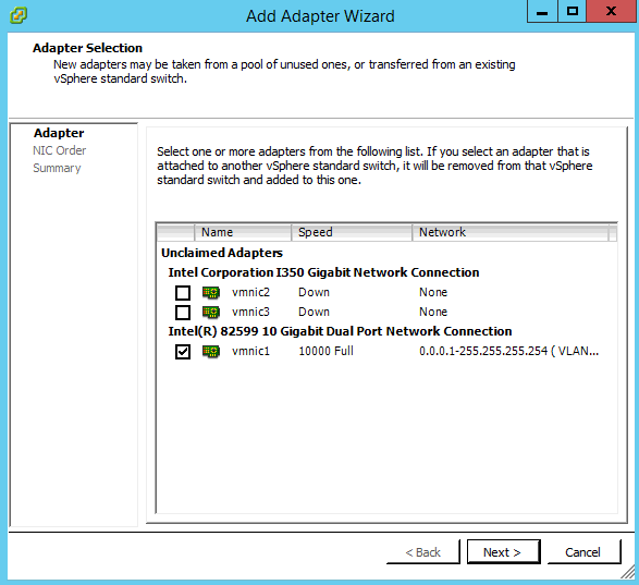
Choose the physical adapters to be used in this vSwitch, create a useful network Port Group label such as iSCSI-1 and assign an IP address that can reach the storage targets. Repeat this process and add a second VMkernel adapter to the same vSwitch. Configure your VMK ports to use apposing physical NICs. This is done by editing the port group settings and changing the Failover order. This allows you to cleanly share 2 physical NICs for 2 iSCSI connections within a single vSwitch.

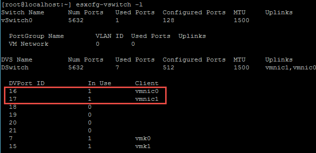
In my case VMK2 is active on vmnic3 and VMK3 is active on vmnic1 providing physical path redundancy to the storage array.

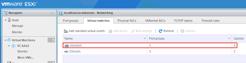
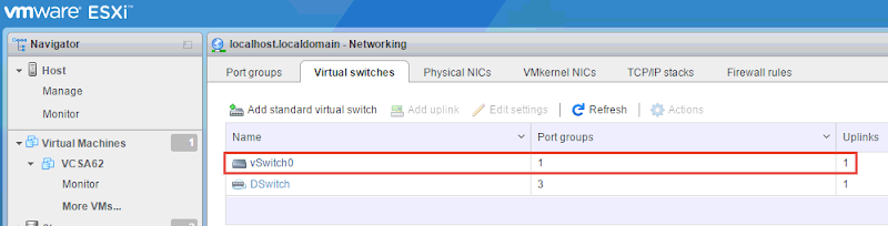
When all is said and done, your vSwitch configuration should look something like this:

Next under the iSCSI software adapter, add the target IP to your storage (group IP for EqualLogic). Authentication needs and requirements will vary between organizations. Choose and configure this scheme appropriately for your environment. For my lab, I scope connections based on subnet alone which defines the physical Layer2 boundary of my iSCSI fabrics.

Next configure the network port binding to ensure that the port groups you defined earlier get bound to the iSCSI software adapter using the proper physical interfaces.

At this point, if you have any volumes created on your array and presented to your host, a quick rescan should reveal the devices presented to your host as LUNs.

You should also see 2 paths per LUN (device) per host based on 2 physical adapters connecting to your array. EqualLogic is an active/passive array so only connections to the active controller will be seen here.

If you run into trouble making this work after these steps, jump over to the vSphere Client which does make this process a bit easier. Also keep in mind that all pathing will be set to Fixed by default. See my How to manage multipathing topic below for guidance on changing this.

iSCSI works very well with jumbo frames which is an end-to-end Layer2 technology, so makes sure a MTU of 9000 is set on all ESXi iSCSI vSwitches, VMK ports, as well as the NICs on the storage array. Your switches must be capable of supporting jumbo frames as well. This will increase the performance of your iSCSI network and front-end storage operation speeds.


How to add datastores:

Once your new datastore has been provisioned from your storage platform and presented to your ESXi hosts, from the Hosts and Clusters view, navigate to Related Objects then datastores. From here click the Create a new Datastore button.

Choose the host or cluster to add the datastore to, choose whether it is NFS or VMFS, name the datastore and choose a host that can see it. You should see the raw LUN in the dialog below.

Choose the VMFS version and any partition options you want to implement. Confirm and deploy.

If presenting to multiple hosts, once the VMFS datastore is created and initialized on one, they all should see it assuming the raw device is present via a previous adapter rescan.


How to manage multipathing:

From the Hosts and clusters view, click the Storage tab, choose the datastore you want to manage, click Manage in the middle pane then click Connectivity and Multipathing under Settings.

Alternatively, from the Hosts and Clusters view (from any level item), navigate to Related Objects, then Datastores. Either click the volume you want to edit or choose Settings from the dropdown. Either method will get you to the same place.

From the datastore Settings page, click Manage and under Settings (once again) click Connectivity and Multipathing. In the middle of the screen you should see all hosts attached to whatever datastore you selected. Clicking on each host will reveal the current Path Selection Policy below, “Fixed” by VMware default along with the number of paths present per host.

To change this to Round Robin, click Edit Multipathing, change the Path Selection Policy, repeat for each host connected to the datastore.


How to rename an ESXi host:

Renaming hosts is one area that the Web Client has made significantly easier (once you figure out where to go)! Select a host from the Hosts and Clusters view, click Manage, click Networking, then TCP/IP Configuration below.

From the DNS Configuration menu, select “Enter settings manually”, put whatever hostname you would like here.

VMware recommends putting a host in maintenance mode and disconnecting it from vCenter before doing this. I did this hot with my host active in an HA cluster with zero ill affects. I did it a few times just to make sure. The other way to do this is via the CLI. Connect to your ESXi host via SSH, vMA or vCLI and run:

esxcli system hostname set –host=hostname

Cool changes in Recent Tasks pane:

Not only is the Recent Tasks pane off to the right now, which I really like, it breaks out tasks by All, Running and Failed individually for easier viewing, including the ability to view your own tasks for environments with many admins. Previously these tasks were all lumped together and longer running tasks would get buried in the task stream.

image


The Recent Tasks pane also provides a new and better method to deal with pop-up configuration dialogs. Ever start configuring something using the old vSphere Client, get 4-5 clicks deep in the pop-up configuration, then realize you need some other piece of information requiring you to cancel out so you can go back to some other area in vCenter? This problem is now resolved in the web client with a cool new section of the Tasks pane called Work in Progress. It doesn’t matter what you’re doing or how far along you are in the dialog. If you need to break away for any reason, you can simply minimize the pop up and come back to it later. These minimized pop-ups will show in the Work in Progress pane below recent tasks.

The example here shows 3 concurrent activities in various states: a vMotion operation, a VM edit settings and a clone operation of the same VM even. Any activity that generates a pop-up dialog can be set aside and picked up again later. This is a huge improvement over the legacy vSphere Client. Very cool!!


Traffic Shaping:

It appears that in the web client you can only apply traffic shaping at the vSwitch level, not at an individual port group or VMK level. Here you can see shaping available for the standard vSwitch:

These settings, while viewable in the VMK policies summary, are not changeable (that I can see).

To override the vSwitch shaping policy and apply one to an individual port group or VMK, you have to use the legacy vSphere Client. Not sure if this is an oversight on VMware’s part or yet another sign of things to come requiring dvSwitching to assign shaping policies below the vSwitch level.


Deploying vCenter Operations Manager (vCOps):

Made extremely easy in vSphere 5.5 via the web client is the deployment of the incredible vCOps vApp for advanced monitoring of your environment. VMware has made detailed performance monitoring of your vSphere world incredibly simply and intuitive through this easy to set up and use vApp. Really impressive. From the home page, click vCenter Operations Management.

On the Getting Started screen, click Deploy vCOps. If you have a valid vmware.com login, entire it here to download the OVF and related files for deployment. You can alternatively point to the file locally if you have it already.

Accept the EULAs and choose all the placement and sizing options for the VM.

A word of caution, do not expect DRS to make a host placement decision for you here during the deployment. The wizard will allow you to select your cluster as a resource destination but the deployment will ultimately fail. Choose a specific host to deploy the VM to instead.

The requisite files will be downloaded from VMware directly and deployed to your environment. Off to the races!

Once deployed, you’ll see 2 new VMs running under the vCOps vApp object in your datacenter.

Once the VMs are powered on and the vApp has been started, you should see new options under vCenter Operations Manager.

First, click the Configure link to open the admin site in a web page. The default login for the admin account is admin/ admin, for root the password is vmware. Configure the initial setup to point to vCenter and the analytics VM which it should detect. Install the certificates as prompted and continue through the registration process.

Once complete, return to the vCOps page in vCenter and click Open, a new web page will launch for you to consume the vCOps goodness. After a short while performance stats should start pouring in for everything in your vSphere environment. Usage patterns and workload profiles can be identified so appropriate adjustments can be made. What you do from here with the data collected is entirely up to you. 🙂

A couple more screens just to show you the capability of vCOps, since I like it so much. Storage at the datastore view:

VM performance view:

Citrix XenDesktop on Dell VRTX

Dell Desktop Virtualization Solutions/ Cloud Client Computing is proud to announce support for the Dell VRTX on DVS Enterprise for Citrix XenDesktop.  Dell VRTX is the new consolidated platform that combines blade servers, storage and networking into a single 5U chassis that we are enabling for the Remote Office/ Branch Office (ROBO) use case. There was tremendous interest in this platform at both the Citrix Synergy and VMworld shows this year!

Initially this solution offering will be available running on vSphere with Hyper-V following later, ultimately following a similar architecture to what I did in the Server 2012 RDS solution. The solution can be configured in either 2 or 4 M620 blades, Shared Tier 1 (cluster in a box), with 15 or 25 local 2.5” SAS disks. 10 x 15K SAS disks are assigned to 2 blades for Tier 1 or 20 disks for 4 blades. Tier 2 is handled via 5 x 900GB 10K SAS. A high-performance shared PERC is behind the scenes accelerating IO and enabling all disk volumes to be shared amongst all hosts. 
Targeted sizing for this solution is 250-500 XenDesktop (MCS) users with HA options available for networking. Since all blades will be clustered, all VDI sessions and mgmt components will float across all blades to provide redundancy. The internal 8-port 1Gb switch can connect up to existing infrastructure or a Force10 switch can be added ToR. Otherwise there is nothing externally required for the VRTX VDI solution, other than the end user connection device. We of course recommend Dell Wyse Cloud Clients to suit those needs. 

For the price point this one is tough to beat. Everything you need for up to 500 users in a single box! Pretty cool.
Check out the Reference Architecture for Dell VRTX and Citrix XenDesktop: Link